This is turning out to be quite the dive into a rabbit hole. It started out as ‘hey, this is cool, I should see if I can do this’. By now it is a ‘thats a whole bunch of hours that I will never get back’. Unfortunately I am too stubborn to admit defeat ![]()
The stl files are huge and take forever to re-mesh to a more reasonable size or to do any processing on. I also found out that I have to find an stl file that is specifically made for cnc work. Files made for 3D printing are not suitable … I should have realized this way earlier but hey, live and learn.
The journey continues …
@Jens The stl files that I pointed you to on designandmake are made specifically for cnc routers.
Since this was just something I wanted to try, I am reluctant to pay money. I used a file from www.ameede.net which was free but was also specifically for CNC work.
The file I used was quite nice as far as the model was concerned but either it had a lot of issues or Fusion didn’t like it. In any case, I will go looking for another file for one last try.
@Jens What size are you thinking of doing this, LxWxthickness?
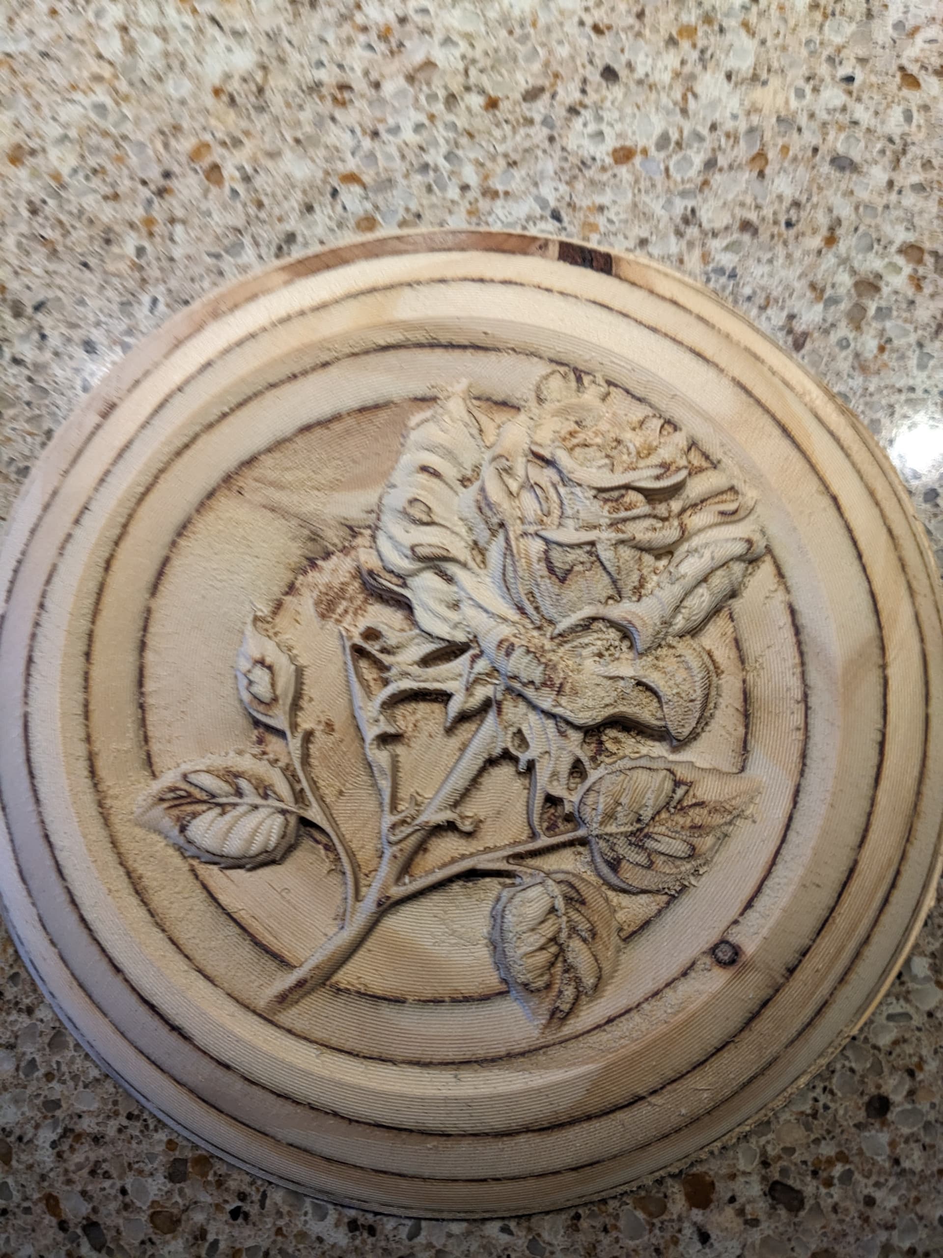
The rose design was 100*120 mm, the overall size was 200 mm in diameter and thickness was 12 mm for my first run.
Note that this is only based on my experiments. None of the dimensions are of any consequence.
I spent several days importing STL files of roses made for CNC. I have been unable to convert these files into editable solids. My last experiment actually generated solids but as soon as I tried deleting any one of the maybe 20 solids that were generated (there was some text), all solids disappeared and I was back to the initial mesh.
Anyway, I wasted way too many hours trying to do this and have now officially given up.
I am too old to learn heavy duty mesh manipulating programs to attempt to convert a mesh to a solid outside of fusion. I also have not a single artistic bone in my body so drawing up my own rose is out of the question.
Needless to say, I am very disappointed in the outcome of this experiment.
@Jens I can sympathize. I know nothing about Fusion/meshes. Your experience would seem to indicate that you cannot simply import an stl file and create toolpaths to carve it. That’s all there is to it in VCarve. It’s good that you did not buy one of the models from designandmake since, even though they are created to import and manipulate in any of the Vectric applications and in other applications directed to CNC wood milling, it seems that Fusion would not play well with them.
I assume that you have watched any of the tons of youtube videos on importing stl files into fusion and converting them to editable models.
Sorry that I couldn’t help.
Thank you for your input, it was much appreciated!
Fusion is ‘officially’ recommending to only try to work with STL files with less than 10000 faces. Some of the imported STL’s were over 200000 faces. There are all kinds of things I can do with STL’s in Fusion - I can for example bring the face count to below 10000 (and get what appears to be a shitty, blocky looking model) but even with a reduced face count, some of the other operations, such as converting an STL into a solid’ do not seem to work correctly. I have worked with many STL’s in the past for my 3D printing efforts but these were much smaller models and they were easy to manipulate. In other words, I am not new to STL’s … but I am also no wizard in fusion so it is quite possible that there are ways to do things.
My goal with the mill is not related to artwork so I am not too broken up with this failure but it would have been nice. Conversely, VCarve is not (afaik) suitable to generate parametric models and that is my primary goal with Fusion.
I was hoping that the free model (trial) of VCarve allowed running small objects but apparently that is not so and I am not spending a ton of money on a program that I would use maybe 6 times a year.
@Jens Understood. You are correct as far as I know. VCarve does not generate parametric models.
I had not been thinking earlier. You may want to try Sienci’s CamLab application. It is free and web-based. It is very basic, but it can import stl files and export gcode.
Here is a link to it CAMLab
It’s based on kirimoto.
1 Like
Yet another update:
After many many many MANY hours of frustration and internet sleuthing, I finally figured it out (or so it seems). Turns out that if you ignore the fact that a model is an STL, you can actually do the carving with fusion! I did have to go to another program (I used Meshlab) in order to cut off sections of the model I did not need/want (a second rose and a notation of where it was downloaded from). Fusion does have all kinds of mesh manipulation tools so it is likely that I would have eventually overcome the use of Meshlab as well.
All my issues where caused by me trying to convert the mesh model (STL) into a solid body in order to manipulate it and combine it with another solid body. Most operations took literally hours to compute only to fall apart if I took the wrong step. What I ended up is to just place the model (STL) onto the solid model that was the base and go straight to the manufacturing section (ie the tool path generation). Now I thought I had tried this before and it failed but somehow this time around I succeeded. I am not arguing with the fact that it seems to work - I am taking the win and I am running with it!
The next issue which might need some work is the estimated time required for machining. I am currently looking at around 7 hours for the rough machining of a 200mm200mm18mm model!
Apparently that isn’t entirely unusual based on other peoples reports but it seems absolutely insane to me. I am going to try a few things to bring that down a bit but it looks like I will have to wrap my mind around the fact that the mill will need to run unattended with only occasional direct monitoring. I will eventually set up remote monitoring (as I do for my 3D printing) but for now I have to wrap my brain around the idea of my Altmill running without me hovering over it. It will be difficult knowing what I know about the power of the Altmill …
Anyway, there is progress …
1 Like
My word Jens, 7 hours.. for roughing.. that isn’t exessive in your world, it is in mine too.
I have made a project using 3x 800mmx150mmish 3D carves on a 2.5 meter board in that time with time to spare. I did my roughing with a simple .25 upcut and my finish run with a 2.5mm tapered.
The boards were needed as a lower ornamental strip on a wooden “caravan”.
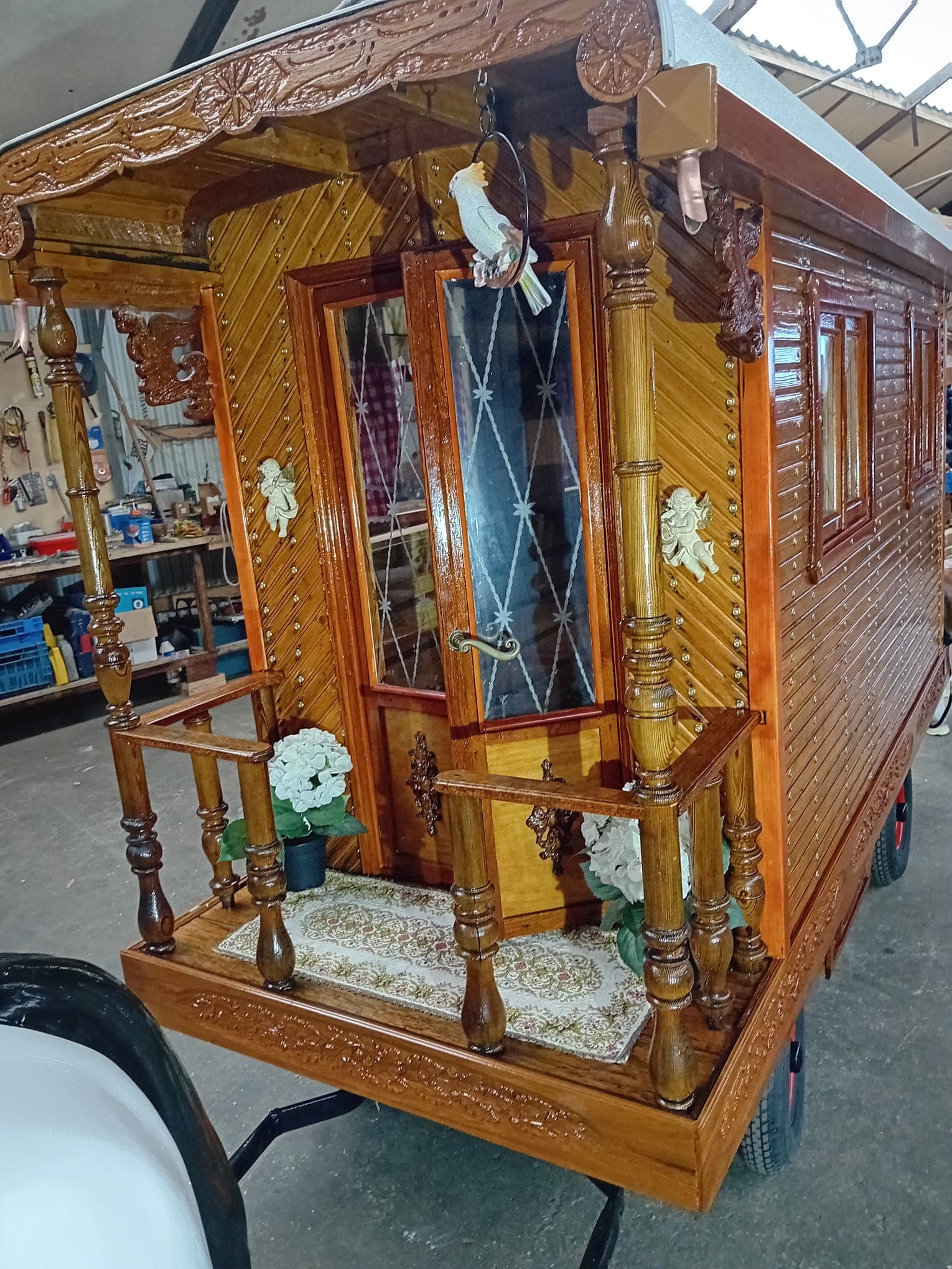
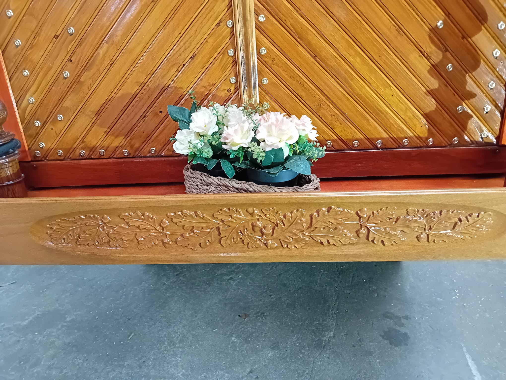
If I can pull that off using a longmill, running conservative feeds’n’speeds because there was nill room for error. You must be able to carve out your rose in .. don’t know but 7 hours.. 200x200.. with an Altmill.. nopenopenope.
1 Like
I brought it down to around 4 hours with a higher step-over but one of the side effects, because I was testing this on particle board, was a lot of little chunks breaking out. So, while the tool path was ok, the end result was disappointing.
Attempt two will be using plywood to see if that comes out better.
@Jens In my experience, plywood, even good baltic birch plywood, makes a very poor medium for 3D carving. The glue layers detract from the design pretty much every time. If you don’t want to try solid wood, go with a good quality MDF. It takes fine detail very well.
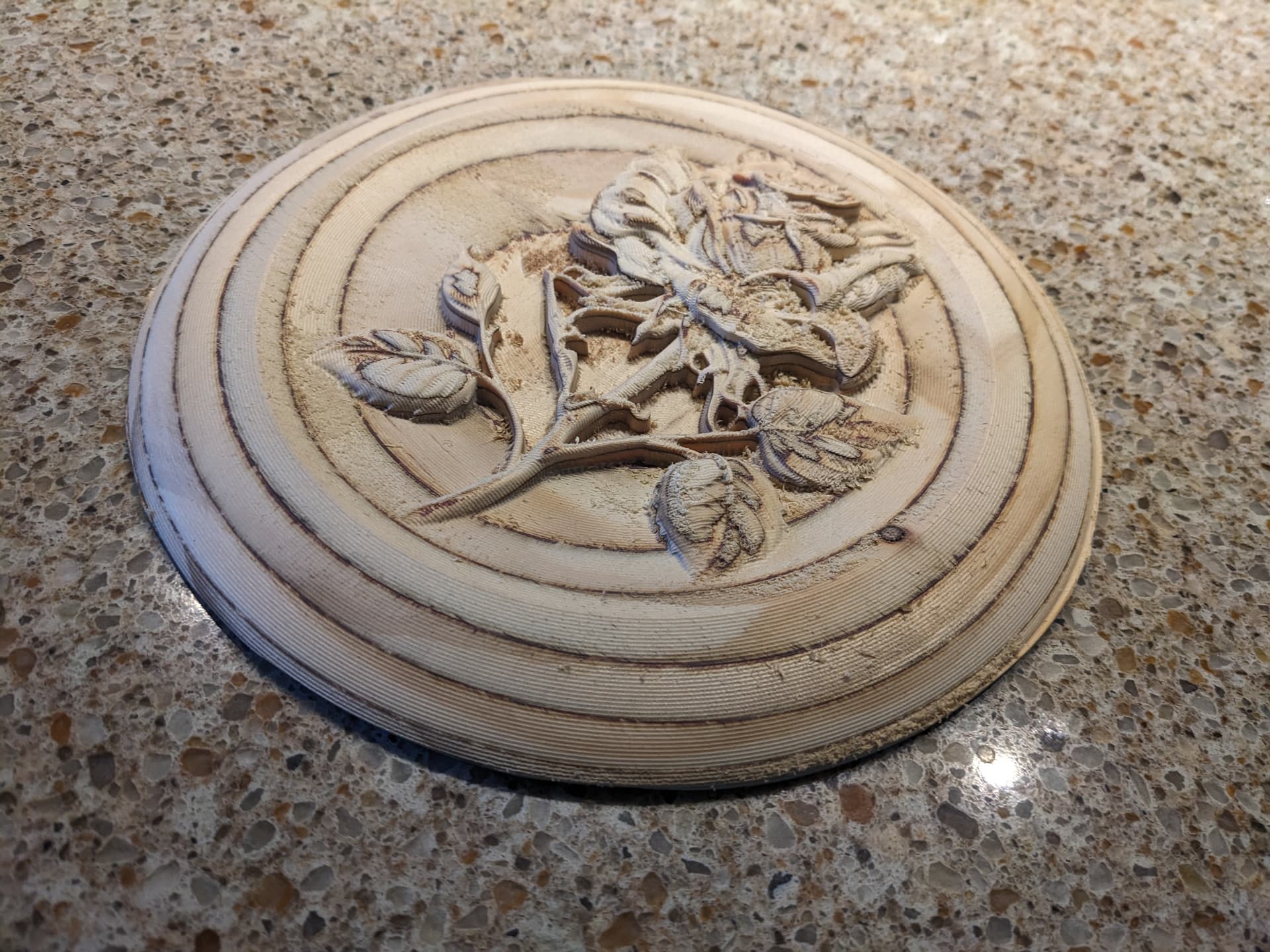
My second go around using plywood was HUGELY improved. The plywood is very old so it has no voids that showed up.
There are some fuzzies in tight corners that are kinda difficult to eliminate but other than that it looks pretty darn good.
I will see if I can find some solid wood for the final product
1 Like
Ooooooh, that is awesome! It almost looks like a dried out rose from a long crumbled bridal bouquet. The layers from the ply make it realy pop.
A nylon or bras bristle will make easy riddens of the fuzzies in the tight corners.
I like your stamina Jens, not giving up, even after announcing you had given up. You’re a biter, aint ya?
A winner
@Jens Congrats on your success, Jens. What did you use for mills?
I used a 1/4 ball end mill for the first roughing pass, the same mill for a semi finish pass and then a tapered ball end mill with a 1/32 dia tip for the detail work.
1 Like
I did something similar and found that using a slightly slower feed rate helped with cleaner detail on the smaller cuts. Also used two passes to avoid tear-out.
I made something similar for my wife last year but added a twist—cut a custom stand for a small digital picture frame
on the CNC and added engraving around it with our anniversary date. It let me combine a personal touch with something more modern, and she loved that it rotates through our old photos. Easy to power with a USB plug and becomes a daily reminder of us on the shelf.
1 Like