Good Evening Everyone, I was one of the lucky early local backers that picked up their Longmill this week. This will be a long one.
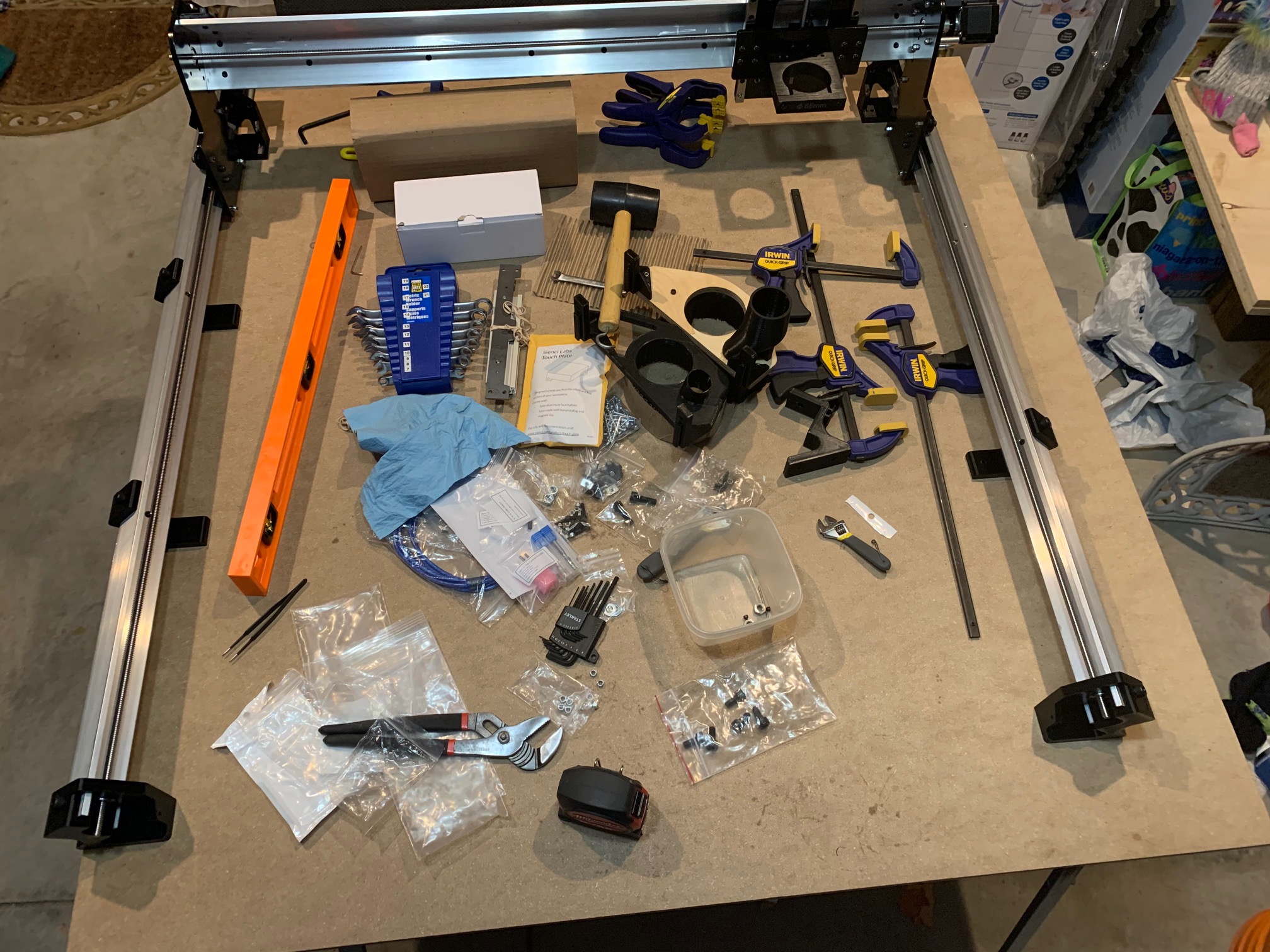
Everything is well packaged and easily identified. The tools in the top right of the photo were my initial expectation of what would be needed based on the first page of the assembly instructions.
I have almost completed assembling the Y-Axis rails when I encountered my first big problem. This one was very likely my fault as I knocked the left Y-Axis rail onto the floor and cracked the left rear foot. I patched it up with some epoxy as I was just a crack along layer lines. I was then not able to slide the leadscrew through the 608ZZ bearing into the coupler for the Nema 23 motor. After checking a number of different things I found the coupler on the Nema 23 motor shaft wasn’t 100% lined up with the 608ZZ bearing. This caused me to be unable insert the leadscrew into the coupler. After trying a few times to slowly tighten the screws and hold the coupler and bearing aligned I was successful just as I was confirming a few things for this post. So I look forward to completing this assembly in the next few days.
I took a few notes on the assembly process up to this point as well as which tools I used I figured I would share with the community.
Tools
- Allen Keys - 4mm and 6mm - the other two sizes needed are provided at the right time. The ones with a 90 degree bend work best, not the iFixit kit in the photo. Just too many bolts that need to be tight and the extra leverage is very helpful.
- Wrench 8mm - for M4 Nyloc Nuts and Eccentric Nuts
- Rubber Mallet - only once
- Chanel Lock Pliers
- Tweezers
- Elbow Grease
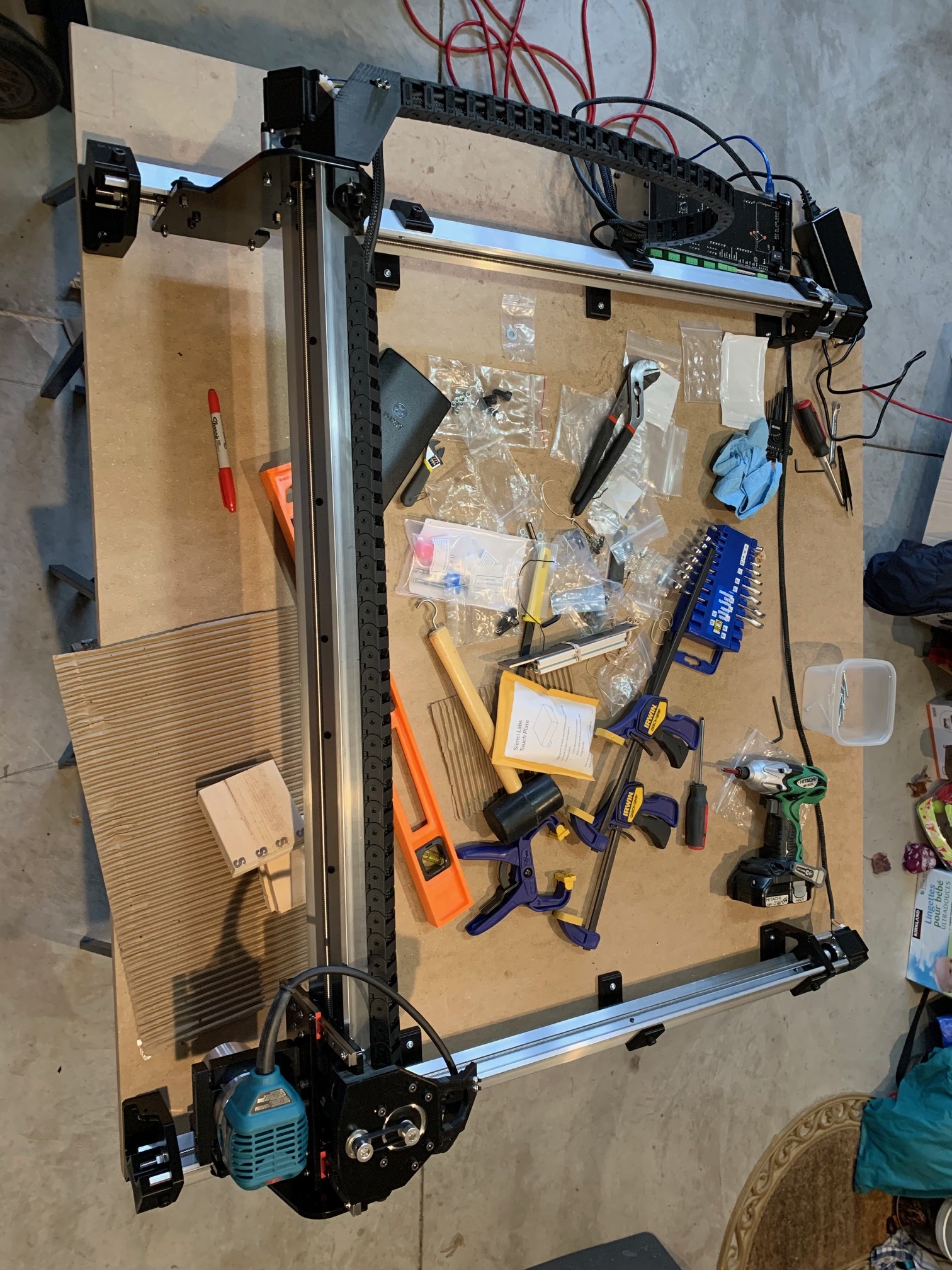
 it’s bigger than expected
Assembly Notes XZ-Axis
- Leadscrew locknut threads are rough and difficult to thread down the leadscrew. Not too big of a deal as that part of the leadscrew is unused if damaged by the Locknut.
- Paint on some holes is very tight to the bolt and can make sliding the Z Motor in as well as to tighten the GT2 belt.
- One captured M4 nut for attaching the Z-Axis Motor plate to the printed mount stripped the 3d printed pocket due to initial cross threading. This was fixed with some Crazy Glue around the nut and it was held in place the second time. I know this is minor, but can be frustrating to newer users. One solution that would make this ‘easier’ would be heated inserts, I have seen them used for building the Opensource Railcore 3D printer and it is more effort than the captured nut but extremely unlikely to have this occur.
- 608ZZ Flangged bearing can be difficult to seat, used Chanel Lock Pliers as a makeshift press to apply even pressure to seat when needed on all Axis.
- V-Wheels have a ring in the centre of the bearing cylinder that was in the way for the bolt for 50% of the wheels. Again, not a big issue as I just used a small Allen wrench to move them sideways back into the bearing, but a heads up for newer users.
- 8mm washer for X-Axis leadscrew is best held in place by tweezers when sliding the leadscrew through the 608ZZ bearing into the coupler on the nema 23 motor (this also works for the Y Axis)
Assembly Notes Y-Axis
- Y-Axis plate powdercoat made attaching it to one end of the X-Axis rail on one side fairly difficult. Used a Rubber Mallet which basically just used the aluminum rail to scrape off the paint. After this it wasn’t too difficult to get it on and the other plate was not as difficult to press on.
- Y-Axis rail attachment could use a bit more information in pictures as well as some instructions. This was the part that I was working on when the left rail fell onto the floor. I was trying to figure out what the pictures and words were suggesting for the assembly method. The solution I used was to lean the XZ-Axis onto the Router Mount and slide the Y-Axis rails in from the back. It was still difficult to manage single handed but nothing else fell on the floor.
- Attaching Y-Axis feet can make threading the leadscrew easier as the Y-Axis is a bit more level, but either do not seat the 608ZZ bearing on the front feet or attach the front foot after the leadscrew. This can make threading the leadscrew a bit more difficult and likely why the instructions say to attach it after the leadscrew.
One last assembly note is on the captured nuts. It was best for me to thread through a bolt from the other side and then pull the nut into the hole. This worked for placing all the nuts in their place, even the one that stripped the hole.
Machine is very rigid at this point, even though its not attached to the wasteboard.
5 Likes
Thanks, looking forward to it.
So I have the Longmill connected to UGS on a laptop and have it attached to the wasteboard. The movement forward/back and up/down look great and coming from a 3D printer issuing two consecutive Y axis moves of -400mm was exiting. I had to check the measuring tape each time before I issued the command. I hope in the next few days to get some saw dust flying on one of the example projects on the Longmill Resources pages. The longterm plan is to have the machine on a rolling table with a Raspberry Pi + 4" LCD touchscreen + wireless keyboard, but that is after I have a better understanding on how it all works together.
I wanted to share a few more things from assembly, in no particular order.
- Fits onto a 3/4" MDF board cut 48" x 49" (4’x8’ MDF is actually oversized 49" x 97", I had mine cut into two 48" x 49" pieces so I would have a spare). But to fit the control board onto the top of the board it is tight to 49". There are no attachment points for the control box to attach to the wastebaord, I am still trying to figure this part out, but that matters more once I get the table built around it.
- Stepper Motor Cable for the Z-Axis Motor has about 10" that come out of the two drag chains, this limits the placement of the control box. The Makita router cord has about 18". I am now planning adding a power bar onto the table, I hadn’t really thought about this part up to this point.
- Z-Axis Motor connector needs to be pointing away from the leadscrew, this gives another few inches at the end of the drag chains.
- X-Axis Motor in my last picture was on the wrong side of the rail, this would have made the cable even shorter than the Z-Axis Motor cable. I moved it to the left side of the machine.
- Opening tabs on the drag chains to route the cables is easiest with a 1/4" flat screwdiver to pop open each tab. put the screwdiver under one tab and on top of the next tab. I haven’t threaded drag chains before.
- Attaching the drag chain connectors to the 3D printed mount I used a 3mm Allen Key and an adjustable wrench holding both nuts.
- Driving the particle board screws into the inside front feet (second screw on the first side, last screw on the second side) my impact driver ran into the mount. I finished the screw with a screwdiver, this could also be done with a longer bit or extender.
- Wires into green screw terminals are tinned inside the terminal, I know that different countries allow this and others do not. Just a heads up to anyone who may be in one of those countries, or do not feel comfortable with that. From what I understand the concern is that solder is very soft and can ‘flow’ under the pressure of the screw terminal leading to a looser connection. It’s less than 1/4" on each wire, you can clip the solder off and strip the wire or use a solder wick to desolder. I am currently planning on leaving them as is for now, but may be shortening the DC cable or lengthening the Z-Axis Motor cable as part of my wire management.
- USB port is on the opposite side of the stepper connectors, this makes it a bit difficult with the tightness of the fit onto the MDF board. Currently I have the stepper wires under the Y Rail so the USB cable is pointing away from the machine. This might be an issue if I need to attach / remove the XYZ proximity plate from the board, but I don’t see it as an issue currently.
1 Like
Thank you for posting details, for those of us further back in line it is super helpful to hear your real time feedback on thoughts and discoveries and ideas assembling the system in to place.
Is it feasible to mount the control box vertically under the edge of the table or atop the table?
If it’s not too much to ask, sine the context of some of your comments is a bit hard to grasp without a system in front of us, would you be able to shoot a quick 3-5 minute video on your phone pointing out some of the various things on the assembly itself and providing some commentary on your experience/suggestions for future builders?
Thanks in advance,
-Jeff
This is all GREAT information. While I have no idea when I might receive my Longmill, I will most certainly review you information step by step as I do my assembly. Thank you for your contributions.
1 Like
@gnuthbie out of curiosity what did you end up with for a final Z height if the board you are mounted to is your waste board?
I’m considering putting a second waste board on top of the board the unit is mounted to, so that replacing the wasteboard when it gets worn doesn’t mean removing the machine and risking calibration issues.
Also, if you’re able to share any materials/feeds/speeds info on your cuts so far and thoughts on them it would be greatly appreciated to those of us in the cheap seats who are another month or more from making chips. 
Thanks,
-Jeff
When I got my first 3D printer I found the videos covering the assemblies extremely helpful in getting around the different gotcha moments that would come up. As you can see from my two posts above there are not many things I can keep to a few words, there are definitely things I forgot that a build video would have covered.
As for moving the controller, that is one thing I have been thinking about. The length of the Z-Axis Motor cable is really the only thing that limits where it can be moved to, which can always be lengthened. as of right now I have the box placed in the top third of the machine on the left and that is about as far away from the Y-Axis cable chain that it can move. If the MDF top was 43" wide instead of my 49" it could be mounted vertically on the side of the table, you would just need to make sure that it is shielded from any dust settling from the CNC as it is air cooled. Or drill a ~1.5" hole for the wires and then mount under the MDF top around the same place I have it on a 49" top.
The specific Z height is a very tricky issue to nail down.
The measurement from the bed to the X-Axis Rail is about 105mm. The Z-Axis Travel is approximately 140mm, probably a bit more as it’s a 200mm leadscrew and about 30mm used up at the top with the motor.
The reason why it’s more complicated than just measuring is the length of the router bit and how low you mount the router in the router mount. This can change that number 0mm-150mm easily.
What I have thought about for a future version of the table is to have the centre between the rails basically empty to the floor. The table would provide the support and calibration. Then I can put my wasteboard in at the ‘normal’ height but then remove it as needed. The one thing I would really like to play with is CNC joinery for boxes. Basically you mill the end of one board to fit what you cut into the face of another board. Kinda like a dovetail or box joint jig and a hand held router, but more intricate. For that there is usually a hole milled out of the wasteboard and then the board is clamped in at 90 degrees or 45 degrees.
This would be a future table, the current one is planned to be more basic. But I can tell you from experience the attachment of the machine to the MDF is very easy going by the instructions. After the wiring and download of UGS, it was probably 5 minutes. I put the machine at Y Max against the motors (manually, I hate hearing steppers skip), move Y -200, screw in one left front inner screw and one left back inner screw. Screw in the last two left inner screws and then the four left outer screws. Screw in the right back inner screw, move Y -100 (total of -300 from Y Max). Screw in the two right middle inner screws, move Y -400 and screw in the last right inner screw. Then screw in the last four right outer screws. It took me much longer to type than to actually do it, but I don’t plan on doing it again until the next table.
1 Like
Thanks, I know notes from the people who first made the two 3D printers (Tronxy X5S and Ender 3) I have really helped me though the many different things that came up. Since I was one if the first people to get theirs I hopped to provide the same type of information that helped me.
1 Like