mulling over ideas on how to Cut a Full 4x8 sheet without adding dowels in the sheet itself. was thinking about an outfeed table frame thats mounted to existing frame. that has precise idexed flip up stops for 24" and 48" and also at 0" on the table. that way you push sheet against left rail. and slide to the 0 stop. do a 4x4 tile. then slide sheet forward to the 48" stop. and do the 2nd tile.
1 Like
Cool idea. I have not tiled anything yet but from what I have read, you need some sort of overlap. Good thing that the Altmill can cut a tad over 49"
Keep us posted about your progress.
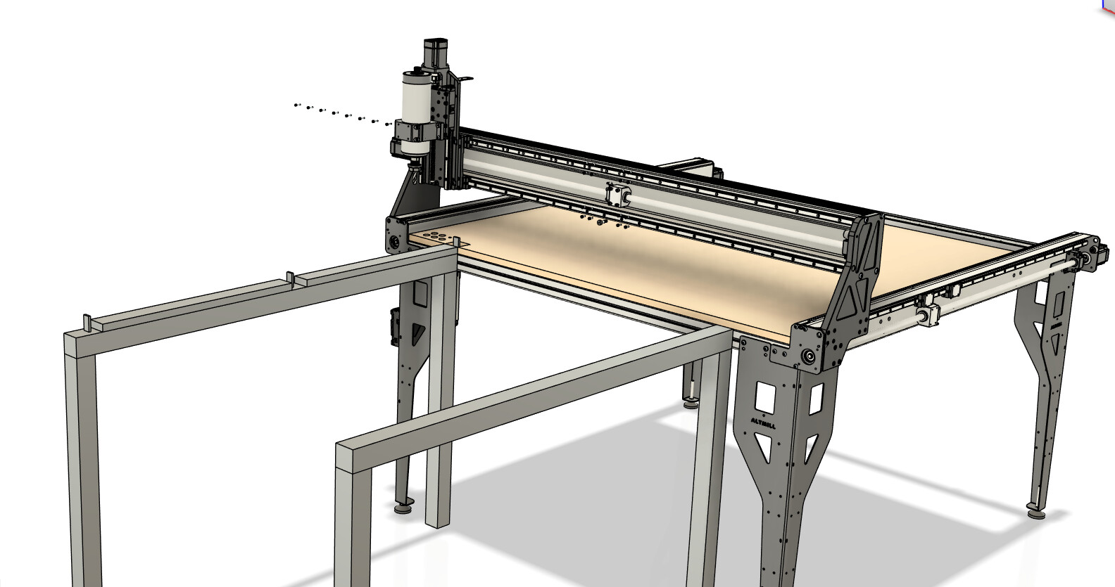
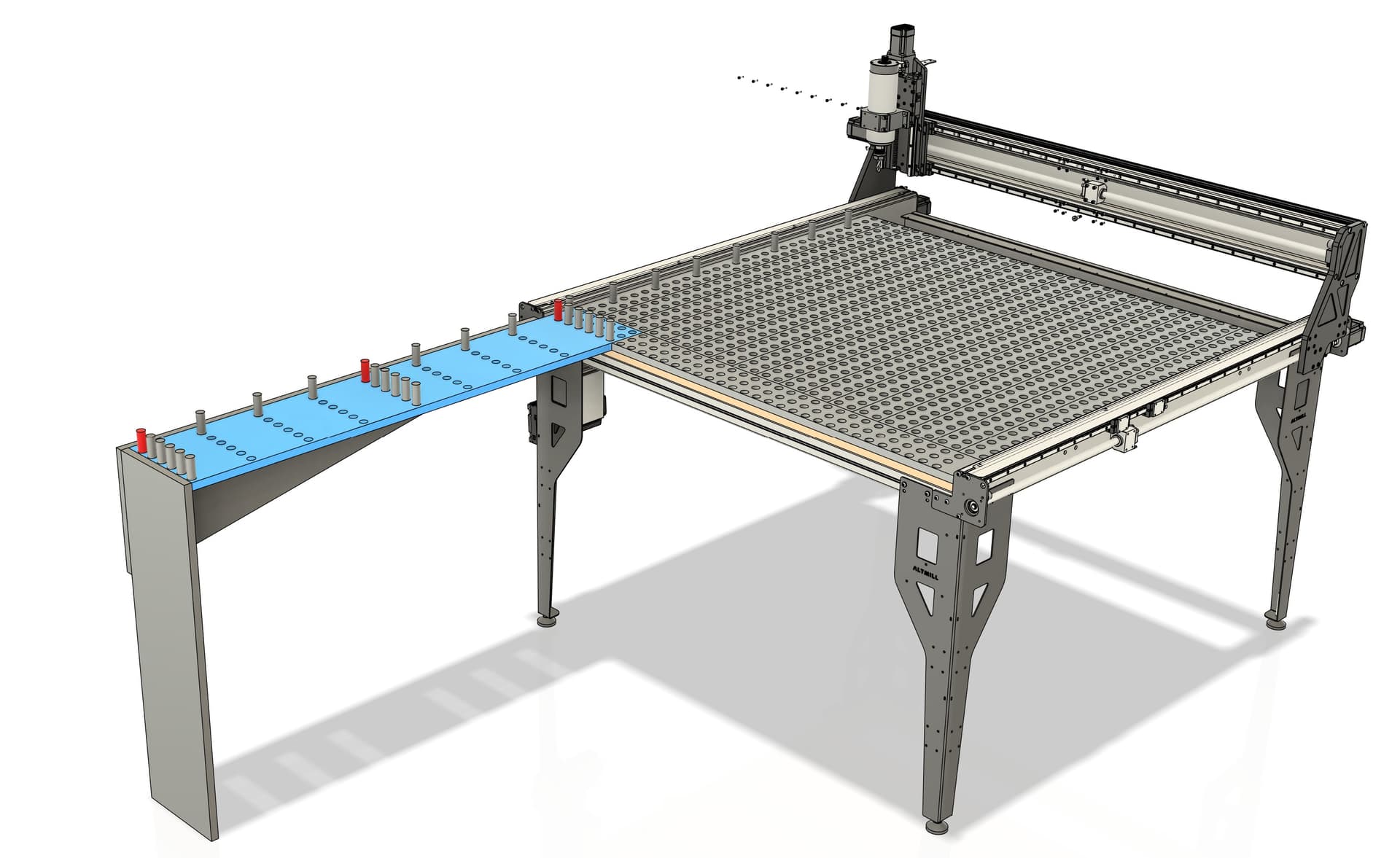
I think this might be a better idea.
The Spolboard is two layers of 3/4" MDF
the bottom layer has Dog holes cut 1/2" Deep. Spaced 1.5" or 2" apart in both directions
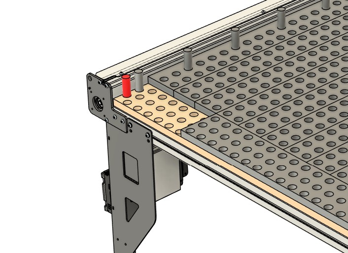
the Top layer of MDF Spoilboard is made up of several differet sized strips all with matching through dog holes. A front edge running horizontally and then long strips running to the back of X Axis
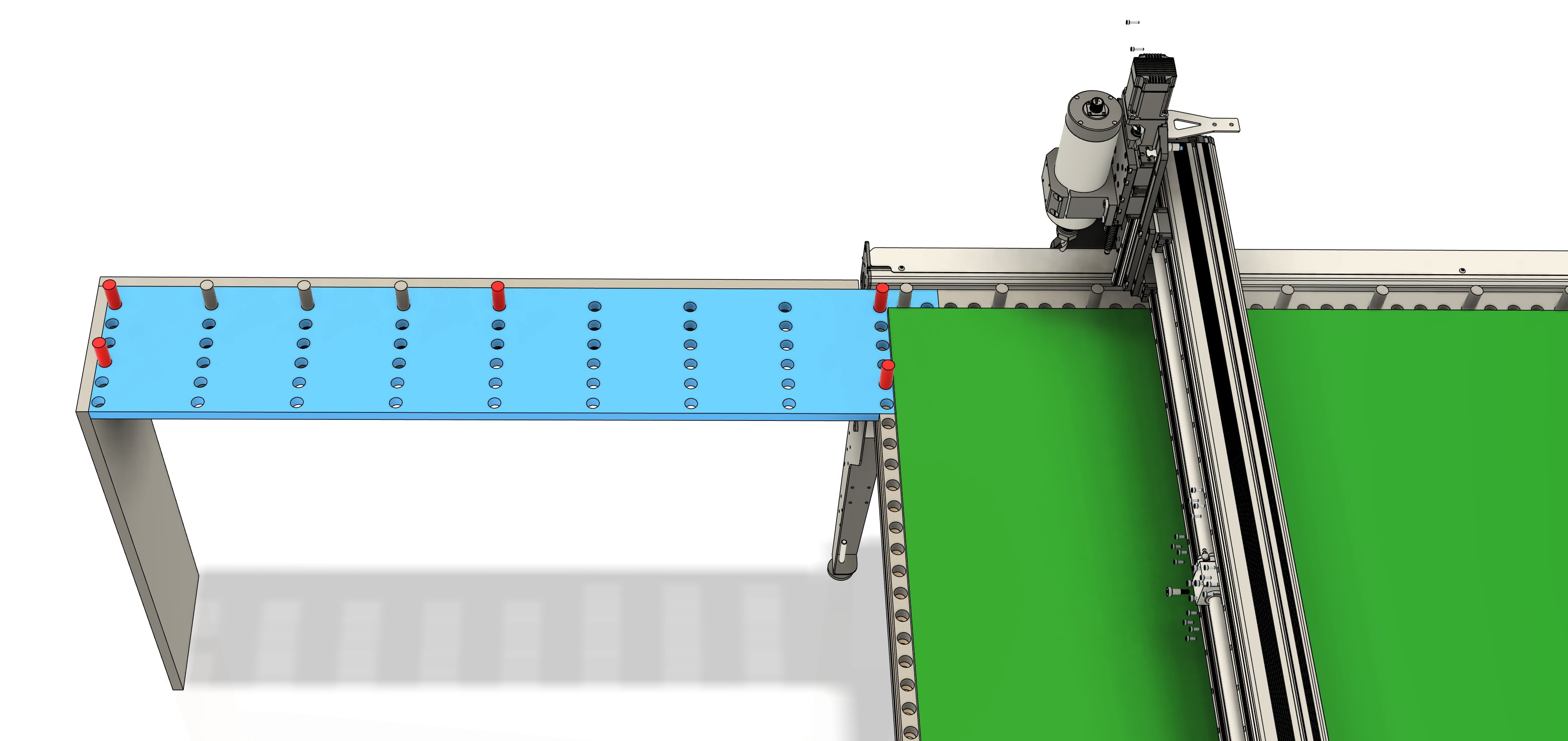
An extension Table with dog holes can be added to slot into this area. with dog holes making a left fence and also tiling increments 3,65,9,12,24,48" whatever is needed
1 Like
Seems like a reasonable way to go about it to me. I guess it all comes down to how square the rail is and how accurate the stops end up being.
I think even if the stops don’t end up at exactly the right length, as long as you know what length they ended up at, you could compensate for that in your CAD/CAM software.
I’ve always liked that Sienci’s machines have a larger working area than advertised. My 30x30 LongMill has ~31.22’x31.99’ (793x838 mm) set as soft limits. I think it’s pretty rare to get more than advertised nowadays.
@MrExo3D Your second idea landed while I was writing this answer.
I like the dog hole idea because it should end up square by design. I’ve been considering adding dog holes to my current T-track setup. Probably the only reason I haven’t is because I’ve never used dog holes for anything. The thing that makes me want to try them is because if they are all cut with the mill then they should be square to the mill and can be used for fences like you said.
With your two layered system the attachment on the front overlaps so a couple dogs at either end should make the whole system square and accurately spaced. It looks likes more work than the first idea but I think it will lead to a versatile setup. It’s a pretty clever idea if you ask me!
1 Like
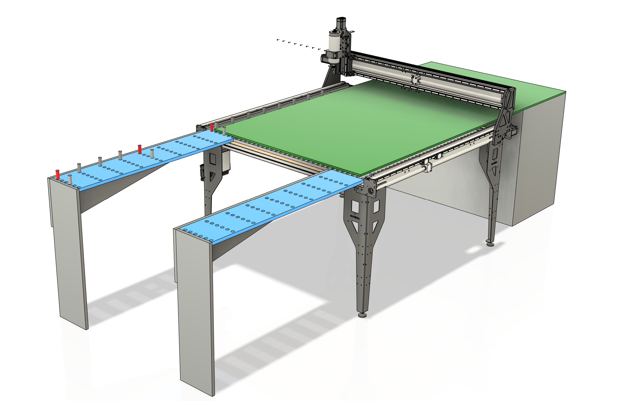
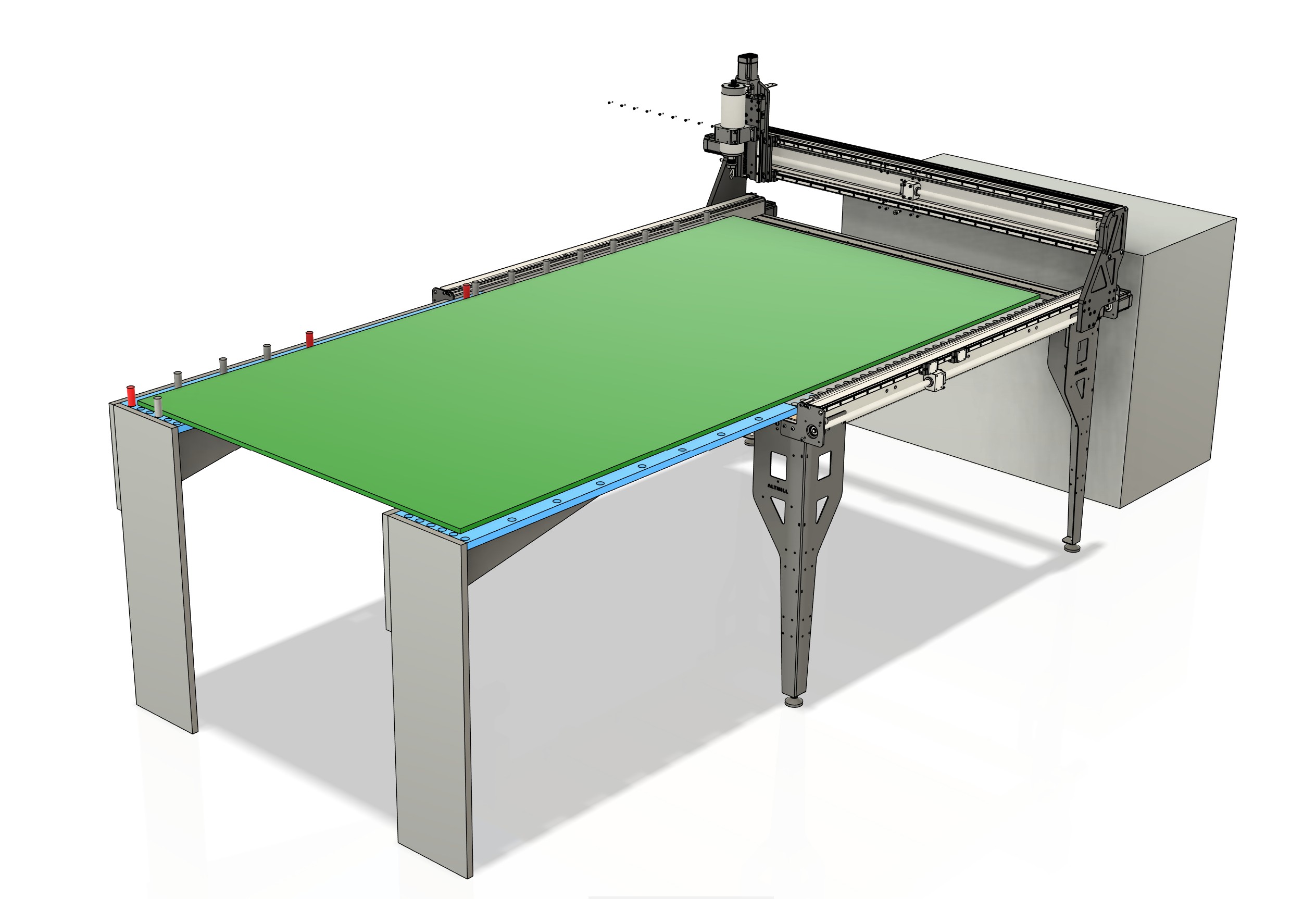
I also like this as the front horizontal strip can be removed for a Vortex rotary axis to be inserted
The first render is something that comes close to my “cheap ass tiling jig” solution for creating feed through signage. I have created a 75inch sign with it. I tested to see if I could still control the lenght dimensions of the sign and came out perfectly 1964mm as per design.
I did however not use the complete y axis for cutting but opted for the tile to be small enough (500mm or 750mm) to be able to clamp down the project just outside the tiling area.
I use vectric as my cad. Normaly I use centre zero, but when using the tiling function in vcarve I was forced to use frontleft as the zero position. Something to take into account, if you are going to use a tiling toolpath generaror in your design software.
Are you going to vacuum hold the sheets or have some other method in mind?
Looks realy fancy and I’m certain you have a winner with this.
1 Like
will likely use some edge clamps on right side to push against the dog hole inserts. no air table (yet) ![]()
That gives me an idea! If you make a vacuum table and can reverse the flow you might be able to play air hockey when your not milling! ![]()
2 Likes

I’ve started down this path a bit - what thickness of material are you using? I’ve found it difficult to maintain sheet flatness across 48in with 3/8 and 1/2in Baltic birch ply by just clamping at the edge, and especially by forcing against the stops instead of holding down. Now looking into vacuum solutions. Working with full width material is definitely challenging.
Also as someone else mentioned, you’ll want a pretty significant overlap in tiles, and make sure you understand the tool entry/exits. Getting the math to support it all in the CAM portion of your workflow is a bit of a challenge - I haven’t found any packages that automatically handle this for you so it requires duplicate setups and a lot of manual labor referencing different work origins across the design. Even moreso if you’re attempting to rotate the workpiece 180 in the process to always stick out the table on the same side.
I don’t have a Sienci router so I’m not sure the options there, but IMO tiling requires more or less the same space as the 4x8 sheet, and at the end of the day if you think you’ll be doing a lot of full sheet work it’d be much better to get a full-size machine if possible and cut the whole thing at once. All of the tool changes etc need to be doubled, and even with precision jigging alignment is a hassle. Not to mention some of the machine envelope is used for tool length probes or whatever, and those tend to get in the way of tiling operations.
Looking forward to seeing how this develops. I’ll share through the design I started to use alignment dowels in the margin of the sheet to try and maximize space.
1 Like