I am moving this question from another, unrelated topic started by @jcampsall
Can x/y limit switches be added to BOTH ends by wiring them in parallel ?
I am moving this question from another, unrelated topic started by @jcampsall
Can x/y limit switches be added to BOTH ends by wiring them in parallel ?
First off, I’m a novice in this area but here are my thoughts. There are two basic types of sensor/switch circuits, normally open (NO) and normally closed (NC). There are also two ways that they could be wired, in series or in parallel.
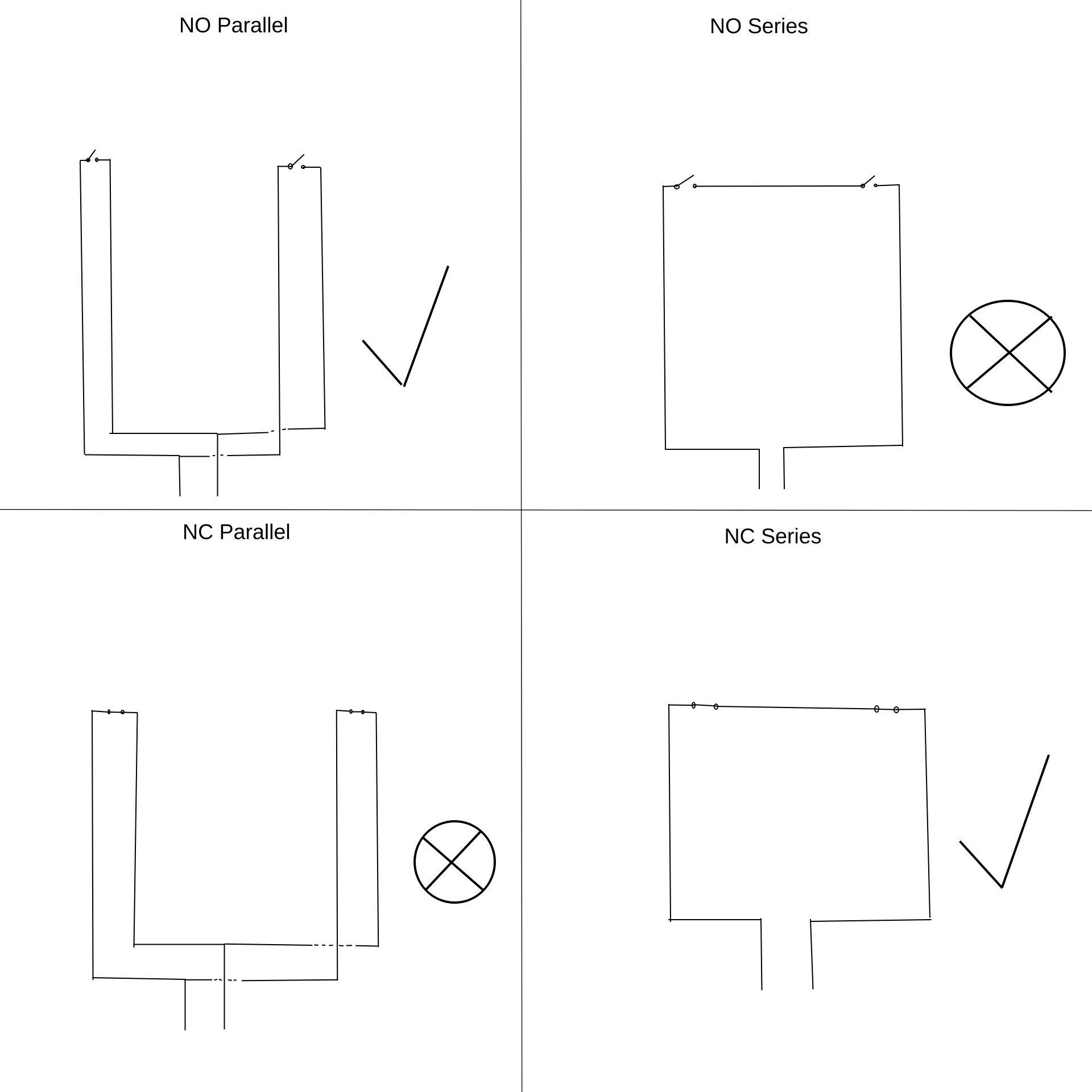
I’ve created a drawing to visualize the four circuits. The two with check marks I think would work and the two with an X in a circle wouldn’t.
NO Parallel: Closing either switch completes the circuit. Success!
NO Series: Closing one switch doesn’t complete the circuit. Failure.
NC Parallel: Open one switch and the circuit isn’t broken. Failure.
NC Series: Open either switch and the circuit is broken. Success!
In any case the control board would only know that a switch was triggered but not which one. The control board would need separate wiring for each switch to know that.
Like I said, I’m not an expert but this is correct to the best of my knowledge.
Switches, yes (easy, simple dry contacts). Inductive sensors, also sort of yes, but in practise its tricky so usually not recommended. Because they are active devices wiring their outputs in parallel does not always work as intended.
The best option is actually single limits, to Home against, and then Soft Limits to restrict moves after its been homed.
That is better than dual limits because instead of relying on a switch to function when machine is already moving full speed toward its boundaries, Soft Limits gently, and kindly, constrains wrong moves long before they even happen
@peter_vanderwalt Thanks for this, Peter. I was not the member asking the question, but I can see how you would believe that. I moved a post by @jcampsall here. I’m sure that he will see your input.
Thanks very much Peter ![]()