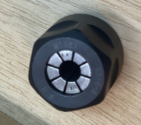
Altmill spindle ER16 collet nut - when ER16A isn't ER16A?

I purchased a couple of dozen ER16A collet nuts earlier this week, for use on my new Altmill CNC router with RapidChange ATC.
They came today, and the Haas nuts don’t fit - the Haas nut threads are a mm or more larger diameter than the spindle, and the nut itself is physically larger than the Sienci one. The Haas ER16 collets themselves that I also purchased are the same size as those supplied by Sienci, and fit in both nuts…

I am surprised - I was unaware that there were multiple sizes of ER16A collet nuts, and I can’t find anything on the Haas (or other) site that says anything about size differences.

Anyone have come clue to hand out before I trust my luck to the chinesium gods of the amazon?

Hey John,

Only now that you flagged this with your topic, I have looked into it and have indeed found two distinct types of ER16 nuts. One with 19mm threads and one with 22mm threads.

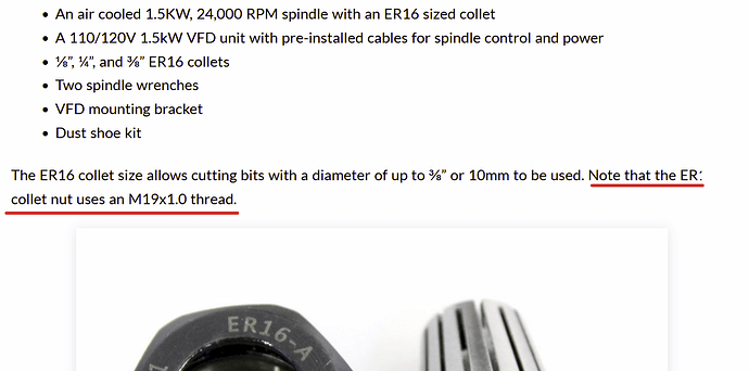
Tugged away in the Altmill spindle kit product details it is mentioned but that is quick to be overlooked.

Now that I know, I will keep this in mind if I ever get to have a spindle. Good to know, thanks for the heads up.

2 Likes

@JPlocher @Spamming_Eddie There are indeed two sizes of collet nuts. They are distinguished by their name. One is an ER16 and the other is an ER16A. Both take the same ER16 collet.

More googling:

The terms ā€œER16 collet nutā€ and ā€œER16A collet nutā€ are often used interchangeably, but ER16A refers to a specific type of ER16 collet nut with a particular thread size (M22x1.5) and is designed for ER16 spindles. While both hold ER16 collets, the ER16A nut is larger and not interchangeable with other ER16 nuts that may have different thread sizes

Except :slight_smile:

I checked the Sienci supplied spindle nut and it says it is an ER16-A
In small print (OK, it all is small print…) it also says M19x1

TL;DR - The Sienci supplied spindle (and the rapidchange ATC unit) use a M19x1 ER16A collet nut with ER16 collets. The key is the ā€œM19x1ā€ and not simply ER16 -vs- ER16A. M22x1.5 nuts will work with the collets (not that it does me any good…), but NOT with the Sienci spindle or the RapidChange ATC.

1 Like

Usual preface, I’m with PreciseBits. So while I try to only post general information take everything I say with the understanding that I have a bias.

Don’t know if this will even help honestly. But in the hopes that it does…

So… ER collets were originally designed by Regofix. It’s actually what the ā€œRā€ in ā€œERā€ stands for. The original design was for a hex headed nut that had the part numbers end in ā€œUMā€ and the ā€œstandard threadā€. After that mostly for things like toolholders a new type of nut was made with a finer thread. They are called ā€œMiniā€ nuts. The mini’s used what is called a slotted or castle style nut.

From what I’ve been able to piece together, other manufacturer’s later came out with the ā€œAā€ designation that meant the original coarser thread and a hex. They then use the ā€œMā€ for the mini. That turned into what was probably 90% of the nut designations (e.g. ER16A, ER16M).

I should also note that for some there’s also an ā€œE/slottedā€ type that is the standard thread with slots. Along with this there are specialty types for VERY high balancing or bearing nuts. In fact as far as I’m aware Regofix doesn’t even make anything with a hex style anymore.

Much more recently there have been these hybrid versions using a mini thread with a hex head. It greatly confuses the market in my opinion.

Regardless, one important thing to take away from this is that ANY nut that is using the mini spec’ed thread has a MUCH lower max torque rating before you start to damage things (bore size dependent). e.g. for a ER16, 1/4" bore, MAX torque:

  • Mini thread: 24Nm/18ft-lb
  • standard/UM/A thread: 56Nm/41ft-lb.

Hope this is marginally useful to someone.

5 Likes

Who makes a collet that actually holds a 1/4" bit snug? Whole we are discussing the er16a

Of the ones I have, only the scienci collet holds, my technics high precision ones will drop a bit right to the floor in a hurry.

ER collets are not suppose to ā€œgripā€ a shank until they are compressed by the nut and spindle taper. With a good collet and spindle even just finger tight should be enough. Usually when they do that it’s either from swarf left from the slotting saw or the collet is ā€œsprungā€.

While I would never recommend doing this as it could effect the runout and life of the collet… Some people will intentionally ā€œspringā€ a collet by tightening it in the spindle without a tool in it. Again, I DO NOT recommend doing this unless there’s a VERY good reason and you don’t plan on using this collet for normal work ever again.

One pedantic thing. There’s no difference in collets regardless of the nut type. They are all the same size and 8° taper. Just wanted to specify so people don’t think they need to find ā€œstandard/UM/Aā€ vs ā€œminiā€ collets in addition to the nut issue.

2 Likes

Being ā€œrecently educatedā€ and therefore ā€œsophomorically arrogantā€ in this area (:slight_smile: ), I’ve learned that a 1/4" collet is expected to be used with both 1/4" and 6mm bits.

A 1/4" ER16 collet can typically hold tool shanks ranging from 0.211" to 0.250" in diameter (6.35mm). ER16 collets, in general, are designed to accommodate a range of sizes within a specific clamping range, usually around 0.039" (1mm). For example, an ER16 collet labeled as 1/4" can securely clamp a shank with a diameter up to 1/4" (0.250") and can also clamp down to a smaller size, down to 0.211".

I have the following on order, and will follow up here with results:

2 Likes

I’m tagging along in hopes of keeping the bits in the spring collets until they’re picked up by the ATC; right now some of them slip out.

I have dropped many a bit during bit changes. Early on I implemented a ā€˜thou must change bits over a suitable surface’ because in a few instances the bit ended up on the concrete floor :frowning:
I too had concerns about how the bit would stay in the collet in those systems that just simply unscrew the collet nut. I think the only reason that works is because the nut is always tightened/loosened while in it’s holder but I have no idea what happens if you are running an extra long bit.
All the CNC (metal) mills I have seen (at least in pictures) drop the entire bit holder with the installed bit and the bit never has a chance to move. I think that’s where air changing systems come in. I also believe you don’t have to set tool offset during every tool change … offset is measured when the bit is installed in it’s holder and never changes after that.

1 Like

Advice I’ve seen is to use a VERY TINY drop of viscous CA glue on the bit as it sticks out above the collet to provide a friction point or slight diameter increase that will hold it in against the nefarious forces of gravity. You don’t want to glue the bit into the collet or glue the collet vanes together!

1 Like

At the day job, we use ER32 collets, and the bit is snug in its spring and the nut holds them both in a cone, so the bit can be measured once and picked up thirty times. But that’s not what I got for ten thousand dollars less. One collet spring got gunked up with pine tar, and you know what? That works! Still springs, but the tar is sticky enough to hold the bit steady. Probably not the best solution, but it leads me to an idea…

This is partially true. A more correct statement would be that a 1/4" bored ER16 collet is within the clamping range of a 6mm. However, the TIR spec and cycle life are not guaranteed and will almost certainly be worse.

From what I can gather from a few of the posts here there seems to be some confusion about the ā€œrapid changeā€ and… I’ll call it ā€œtraditional ATCā€. I’ll list my bias up front here as I don’t like the rapid change. It seems mostly trying to get the cost down for a tool change setup. But with MANY caveats.

One of them being that the tools are free floating until it comes down and ā€œscrewsā€ down on a nut. There’s a few problems with this. The first obvious one that you’re dealing with is holding the tool in the collet without it compressed. Best you could do with this is either have a buffer piece of material under the tool to hold it’s position, or get something it bump up against the the back of the collet where the shank sticks out. I’ve seen a few version of both. Cheapest, easiest one I saw was stretching an oring over the shank in the back. I wouldn’t recommend any of these… But in a best of bad options I’d go with that over something like CA or for that matter ANYTHING that could interfere with the collet to nut/spindle surfaces. Keep in mind, no matter how you do this the stickout of the tool will not stay consistent. This is an effect of the combination of the clamping of the shank while being drawn into the taper from turning. This problem can be made worse if the tool bottoms out in the back of the spindle. Although, you might get it close enough depending on your tolerance.

I had a section here about the potential torque issues. However, it came off as VERY negative and it’s not specifically been asked about so I scrapped it. Short version I don’t like the unknown variable torque and it could be a BIG issue for lower rated collet/nut combos. If someone actually wants a text wall on it let me know.

Final point I’ll make on this is why I care so much about the sprung collet and clean mating surfaces. Short version is that ANYTHING in the interface of the collet, nut, and spindle can offset the collet and cause runout. Short version of runout is it’s how much the tool is spinning off the central axis of the spindle. So now why care about that? The more runout there is the more it effects both the actual size of the cut and in multi-flute tools the chipload. Short version of chipload. Chipload is the width of the chip being cut per flute per rotation. Or another way to think of it is that it the amount each flute is moving ā€œforwardā€ for each rotation. Chipload is probably the most important factor in milling and what all feeds and speeds are trying to get to (in combination with surface speed).

So a quick example. Let’s say we are cutting with a 2 flute endmill at 40IPM and 10KRPM. That works out to a chipload of 0.002" (feed / RPM / flutes). Now let’s assume that we have a collet with 0.001" runout. What will happen in the worst case, and almost always with a tool with a helix (flute twist) is that the runout will cause the tool to move in and out of the cut. So one flute will cut 0.001" and the other 0.003" or the equivalent of 20IPM on one flute and 60IPM on the other. This will get worse with more runout until you are cutting your combined chipload on a single flute. There’s a number of issues this can cause from overloading a tool with a normally good chipload/feed, to getting a bad finish as you are effectively cutting at multiple different chiploads/feeds. At a minimum it eats forces that you could otherwise use as feed in your cut and shortens tool life.

So I highly recommend not to do anything that effects the surfaces of the collet, forces distortion in the collet, etc… and keep all the surfaces clean.

I realized that was potentially a lot of unasked for information. I couldn’t really come up with answer to this that I felt wouldn’t lead here eventually though. So I just tried to summarize it up front. Hopefully it’s useful to someone. If there’s something I can help with or want me to go deeper into, let me know.

4 Likes

Thanks for that. It never hurts to get more educated so if you wanted to add that wall of text about torque it would be welcome. Regarding feeds speeds and chip loads you’re preaching to the choir though I’m a lot more flexible and forgiving on my hobby CNC than the 5’ x 12’ ten tool beast at the day job.

Great info that is hard to disagree with.

That said, I’m not sure we are evaluating things from the same perspective. With my novice machining capabilities and skills, using the AltMill for the projects and materials I envision, I don’t expect to hit the levels of precision you are worried about - not that I won’t strive to get there. :smiling_face_with_sunglasses:

Performing a tool length touch off after every tool change may make up for variations in stickout, an O-ring for the free floating bits, and a bit of trust-but-verify and know-your-limitations could minimize the torque concerns. Or so I’m thinking.

Along with Quinn, Tony and Jason from the Tubes of U, I’m learning from y’all and filling in those pesky gaps in my head that are filled with ā€œI-Dunna-Knowā€. Without mentors and role models, I’ll never know what is possible, learn new things or try to do the amazing. Thanks for setting a high bar!

1 Like

Going to address this first as it’s faster.

Yeah, if you are talking about stickout differences that could get you well into you tolerances. The big issue with it is if you end up running multiple bits to clean up or where you need the same Z level. It’s especially an issue even on a hobby level for roughing and finishing passes on a 3d carve. They are VERY unforgiving of differing tool Z.

If you are talking about the runout perspective, that one will effect you more than you think. If your runout is any significant fraction of your chipload it will at the very least make for confusing variability in your cuts. Especially when trying to tune for a tool or material.

Want is a strong word… But here you go.

The torque issue requires some base information. Before that though, let me be clear that I don’t have or have even been in the presence of a RapidChange. I don’t have anything to go by but the numbers and information I can find from users or sellers. So some of these issues might be resolved or just incorrectly measured.

That out of the way the main issue is what torque is being put on a nut in the rapid change. From my understanding it’s more or less just spinning the spindle while locking the nut in a holder. That will have a huge amount of variation from setup to setup (and I’d assume wear on the holder). It would also be effected by things as simple and common as sawdust or other debris getting on the threads of the nut or spindle.

A competitor to Sienci and seller of the RapidChange did publish some numbers for their version of an ER20 system. As they’re a competitor to Sienci I won’t link it. Although, if one were to google ā€œEasy ATC by RapidChange Test Dataā€ one might find it. In that data they first have 60x cycles with a min/max torque of 12.7Nm and 28.9Nm. Further into it on 10x setting of different shank tools they get a lower minimum of 11.5Nm. The mean range between all of them is 14.95Nm to 22.95Nm. This falls more or less in line with other data I’ve come across. There also seems to be a far amount of variation based on the spindle type and power. Let’s go with this for the examples though.

Now we need some numbers for ER collets. We are going to be looking at the MAX torque for each of different ER sizes, thread types, and bore diameters.

    ER16 Mini
    • 1/8" - 20Nm
    • 1/4" - 24Nm
    ER16 Standard
    • 1/8" - 20Nm
    • 1/4" - 56Nm
    ER20 Mini
    • 1/8" - 28Nm
    • 1/4" - 28Nm
    ER20 Standard
    • 1/8" - 32Nm
    • 1/4" - 32Nm

You may already see some of my issues with this. My 2 main issues here are unless we are talking about the ER20 standard we can exceed max torque. To be fair though this was a unit being sold for an ER20 standard thread. So maybe they have some way of tuning them for each thread and size. Another issue though is that our variability of the actual torque applied is quite large.

The exceeding max torque issue is obvious. This is beyond what the parts are spec’ed for and the spec is with high end spindles, nuts, and collets. This will at the very least lead to reduced life and increased runout.

The variability one is much more complicated. There’s 2 things we have to be aware of with the nut torque.

The first is axial and radial slip resistance. Or how easy is it to spin the tool in the collet or pull it out of the collet while cutting. Unfortunately there’s not good data on this in terms of what is ideal (that I’m aware of). You only see numbers based on max torque listed.

The second issue is how much torque is too little or too much for minimal runout. That I have some numbers on. We have been colleting it and will probably eventually put something up about it when we feel we have enough data. Here’s an example though. This is the average and max runout on the same ER16 1/4" collet with a mini nut and 6 different nut torques. In total it’s collected from 480 points of data. Not enough data points or on enough collets for our taste. But it gives a broad idea and other ER and bore sizes follow this pattern with the exception of high runout on the low side in some cases.:

These are at 2 different measurement points, the face at the front of the collet, and at 1" away from the face. The units are in thou (0.001"/ 0.0254mm). The last torque intentionally exceeded the max torque spec.

Both the slip resistance and the runout variation will change, potentially by a lot, based on the quality of the collet and and spindle bore. Or at least how well they match and the clocking.

All that said something that could produce between 11.5-28.9Nm on the nut is a wide range. It makes for too many extra variables for my tastes.

Again, I could be completely wrong about all this. The example I just laid out is based on the numbers that one of their sellers produced and this may not properly represent the product or current version of it. There may also be a ā€œtuningā€ to not exceed the max torque for the ER size provided. Without some kind of data on what torque it actually produces and how consistently I personally wouldn’t feel comfortable with it though.

Hope this doesn’t come off too negative or harsh. I’m truly not trying to attack a product or even discourage it’s use. I’m trying to pass along what to expect from this with the data available.

Let me know if there’s something I can help with or expand on.
4 Likes

You must have wanted to do a professional job of it because you put in a serious and informative essay. I’m going to read it again, and bookmark it. I will also document my experiences with the tool as is because on my 500$ spindle and 350$ on the ATC, I can afford to burn some bits. I’m betting that mostly it will work ā€œfineā€. In fact, I waited until a few dozen others bragged on it before pulling the trigger. Your critical test will happen soon; roughing, finishing, outlining and scribing on a finely contoured 3d wing shape. All four actions, with four bit types and sizes, must work flawlessly to justify the setup. We’ll see…

Lol, you should see some of my posts on other forums or internal data and notes. This is a baby. Hopefully it’s useful though. Hard to get across some of the points without being long winded and reference ā€œwhyā€. I also did do a fair amount of work to try to keep it as unbiased and neutral as possible.

That said I do come out of a section of the industry where small stuff adds up to failures (sub 0.001" diameter tooling, steel rules die where 0.0280" tipped tooling needs to get 0.36"+ deep slotting with almost no deflection, straight wall inlays in exotic woods and MOP needing zero glue lines with 5x loops, etc.) . So I acknowledge that it’s impossible to completely remove my bias. On the other hand though, it’s given me far more insight into where a lot of the variation comes from in more tolerant scenarios.

Probably depending on your tolerances and margins. Might have to increase those though depending on where you are starting. Even just from the torque example a VERY good collet could pickup an extra 0.001" of runout at 2" and require that extra force in chipload to be available without compromising the cut or tooling.

That is more a practical test within your:

  • Tolerance - Z levels, dimensional accuracy, cut quality, etc.
  • Margins - % of max force/chipload and axial/radial width used to maintain tolerances, etc.
  • Tooling - flute count, geometry effects to margins/tolerances, required stickout, tool rigidity, etc.
  • Material - force to remove cubic material per flute, range of chiploads within tolerance, etc.
  • Equipment - collet grade/runout, spindle type and power, maybe machine rigidity, etc.

I’ll still be interested in it. However what I would really like is more empirical data on the torque being applied. The empirical data lets it be mapped better against all the other data points. Don’t know if you have the tools. Would need a torque wrench with about a 10-30Nm range for this size and thread at a minimum.

Good luck on your project, let us know how it goes.

1 Like