Calibration: An idea to make it more precise

After bolting together and mounting my Longmill temporarily onto its base, I decided to calibrate it, using the gSender’s Calibrate function (you can find it on their pull-down tab).

But because I was looking for as precise a setup as I could possibly get, I decided to use an old school method for marking the three points where the machine was aiming: carbon paper!

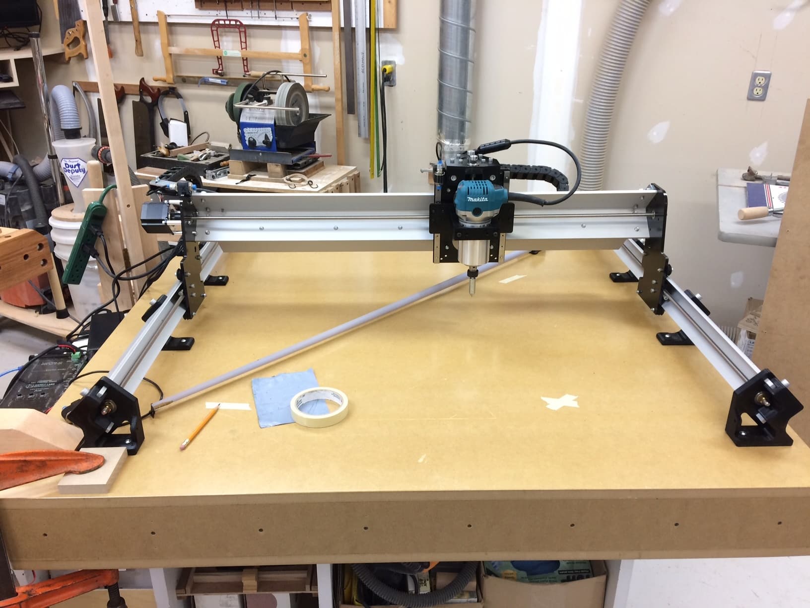
As you can see in the above photo, I have a pointed router base setup bit (that I use for positioning the bases on my hand-held routers, but anything like it would work as equally well), mounted in the router. After moving the router to its first position, I lower the bit until it’s a few cms above the table surface, then lay down a piece of masking tape beneath it. I slide the carbon paper between the bit and the masking tape, then lower the bit until it is just touching the paper. This leave a very precise dot on the tape. I do the same thing for the two other positions.

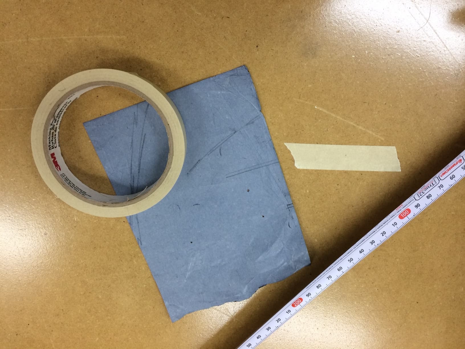
The above photo shows just how small, yet very visible, the dot on the masking tape looks. I consider the carbon paper dot method to be considerably more precise that attempting to place a piece of tape with an X on it exactly below the bit, or to mark the X on the tape after you’ve positioned the bit close to the table. It’s also faster (at least it was for me) .

Hope this helps someone out.

All the best,

Marty
Kingston, ON, Canada

4 Likes

Great idea Marty. I think I am going to use it when I am ready to calibrate. Thanks for sharing!

I turned down the top end of a very sharp pencil so that it would fit in the router. Lowered the Z to make contact with a sheet of hard white card stock. The program left a trace that could be measured accurately.

1 Like

@oidar Welcome to the group, Edward. Excellent idea for accurate marks.

One thing that has not been mentioned in all the threads about calibrating our Mills is the method use to actually measure between the marks left by whatever means we use to make the mark. When owners are talking about trying to take a Mill which is out of square by 1mm and making it more square, it is critical that the method to measure the diagonal can yield precise results. Just a thought.

I agree that accurate measuring is essential, and that to do it precisely is also very challenging. For my purposes, I use: the software, my aforementioned method of placing a small dot precisely on the spoilboard, a quality, metric scale tape measure and my spouse’s assistance. I have her hold one end of the tape over the dot at the 100mm position, and I’m at the other end taking the measurement (and of course subtracting 100mm from my readings). I also don’t rely on memory, but record them on a diagram before plunking the results into the computer. We do this for the A-B, B-C and A-C (diagonal) distances.

Another method, without having to rely on geometric calculations (I don’t want to state how many years it has been since my education in those areas was undertaken…), you can just go ahead and make a point at each extreme corner of your spoilboard, using whatever method you feel comfortable with. (I’ll stick to my carbon paper method). Start first to see if the distance between the left side Y points are the same as those on the right side. To do this very precisely and without taking any measurements, use a set of trammels similar to these ones and fasten them to the ends of a stick long enough to enable you to set a trammel over the marks you want to check. The point is, that knowing the number is secondary to knowing whether or not they’re the same. A set of trammels will give you that.

And if the distance between the far and near ends along the Y-axis are the same, and, if the distance between the diagonals ( that is, the back left dot and the front right dot and the front left dot and the right rear dot) are the same as each other, then your CNC is indeed precisely set.

Again, I don’t have enough experience with CNC operations to state whether or not if both the Y-axis measurements are the same, that a 1 to 2mm deviation between the diagonals for a 30 X 30 Longmill are operationally acceptable. However, I suspect that with all other things being equal (e.g., the stepper motors, screws, V-wheel adjustments, etc. are set correctly and working properly), I would be very happy.

What do others with experience have to say about the use of trammels and, as well about my thoughts on diagonals being out by a few mms?

2 Likes

@ApexWoodworks Sound ideas, Marty. As I have the LV trammels and poor eyesight, I used them when I last checked my Mill. Using a jog of 600mm in each of X and Y, gSender told me that I was in good shape, but that if I wanted to be perfect, I could move one of the Y gantries .55mm. I passed on that advice. :grinning:

That said, I don’t criticize anyone who figures that .55mm is too far off square for their comfort. I’ve just found that, over the hundred or so projects that I’ve done, it has not had any visible effect on the quality of the carvings. (Of course, I did start this out saying that my eyesight was poor. :wink: )

1 Like