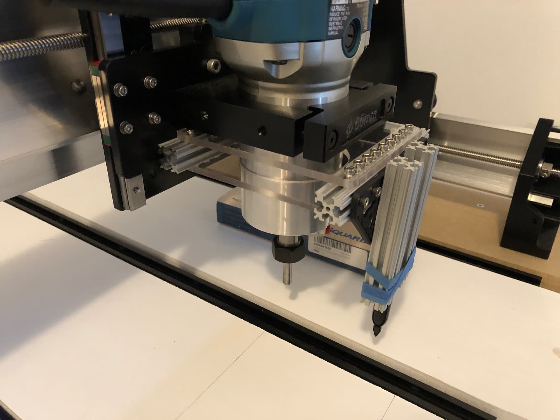
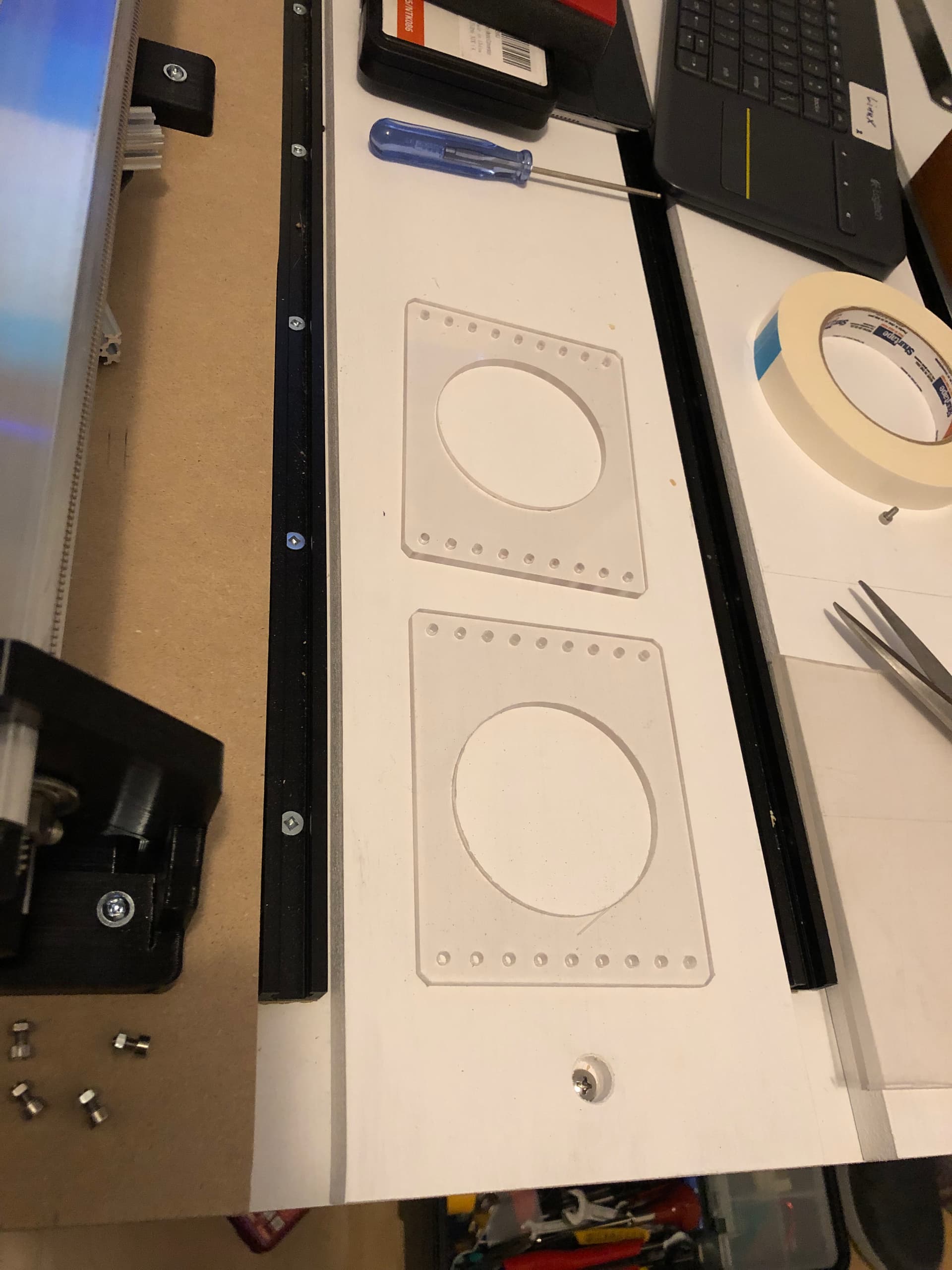
I recently added a pen mount to my Long Mill using a dual plane compliant cantilever. This is very simple, consisting of just two parallel plates, but keeps the pen vertical while allowing for a small amount of springiness. It has zero backlash but a very small (and negligible) offset in Y when deflected. The plates are PETG with a cutout in the center for the router, bolted to a small length of aluminum extrusion (15mm makerbeam) at each end. Wood blocks could be used in place of the extrusion, the main point is they need to be a uniform height and stiff.
1 Like
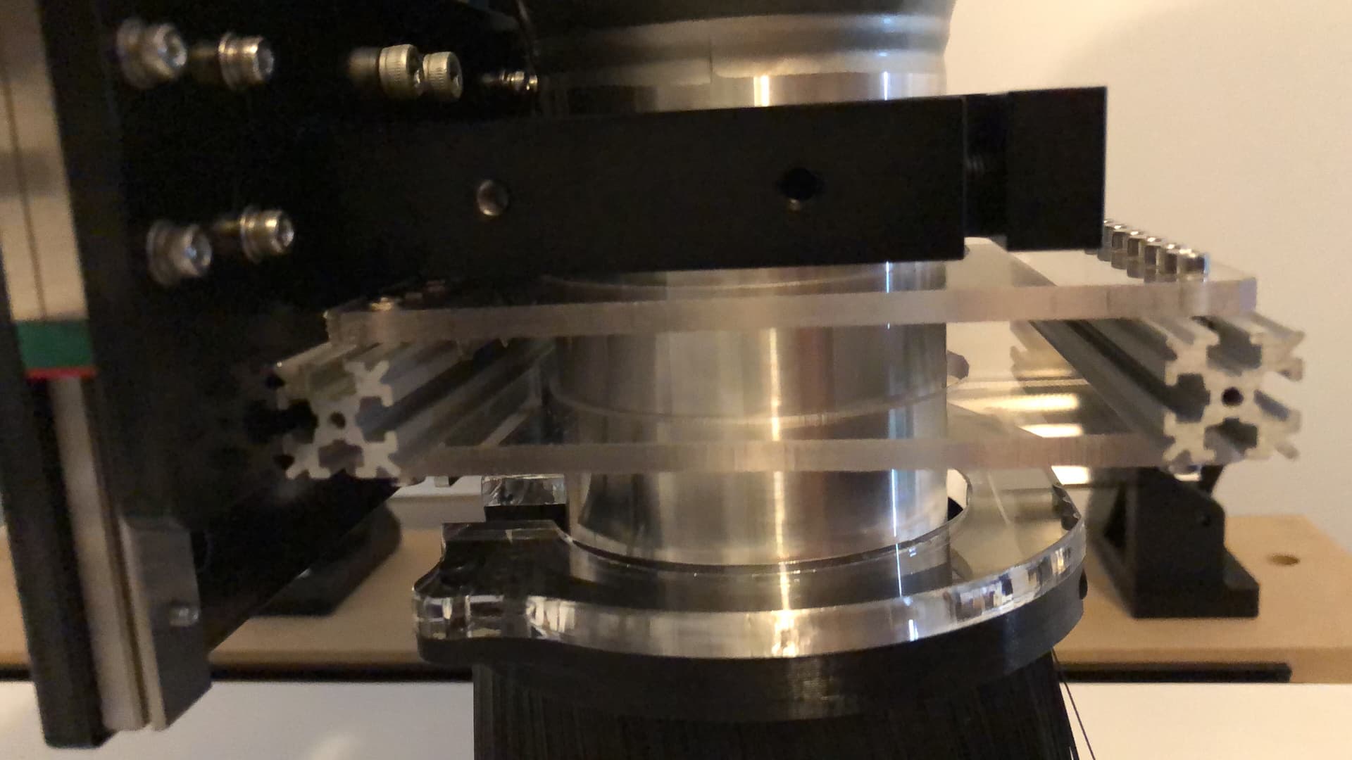
More pics. This makes it clearer how this works. The 5mm PETG plates I used are slightly flexible. This is a dual-cantilever compliant mechanism, so think of it as two parallel linkages. It allows the pen some vertical travel while keeping it perpendicular. Pens need a small amount of downwards force, and the compliant mechanism provides that. When the pen is pushed upwards there is zero play side to side and only a tiny deflection in Y. This is much less than the thickness of the pen, and is less than the play in other solutions (sliding spring-mounted shafts, for instance).
1 Like

So I will say the bolts shown here didn’t work out, there was not enough clearance under the router mount. I needed to drill some off-center holes in the extrusion and use low-profile button head bolts on top to squeeze it in.
The pen holder is just something I put together with spare makerbeam parts. Two rubber bands squeeze the sides together to hold the pen firmly, but if you goof and crash the head the pen will pop out (intentionally). It unbolts and slides off when I don’t want to use the pen.

1 Like
1 Like
Test drawing with the standard Long Mill starter gcode and a sharpie. The shallow cutting depth in this gcode example is perfect for using a sharpie. For a drawing surface, I put a piece of MDF on top of my wasteboard and taped paper to it.

1 Like
I see how this cantilever works, but what I don’t see is how much force it takes to deflect it compared to how much force it takes to dislodge the pen from its friction mounting.
I’m looking at your very well thought out design and wonder how much that deflects on a typical drawing surface. Or even how much deflection is even needed to keep the pen in place.
Can you put a scale under the pen and get some values? That may be something useful to you, also.
I don’t mean to be pedantic, but too much down force has squash the tip of a pen I used so the lines weren’t consistent. This experience made me stop, consider what this might do to an expensive marker and think about how to apply this to my CNC.
Now I see that you’ve some up with an interesting design.
Unfortunately I haven’t had much time to play with this (or my CNC) lately but…
- The amount of force will depend on the deflection and the thickness of the sheets. So you can make it as “light” as you want by using thinner sheets, or more flexible sheets. I used PETG because it has more flex than acrylic, BTW. This will not affect its vertical motion, as long as both sheets are the same. In general, the force should be very consistent, at least.
- Controlling deflection depends on the platform being flat if you use open-loop control (e.g. typically how basic CNCs work). Shouldn’t be a problem if you ran surfacing on your bed already and your paper is flat.
- However, since the force should depend on the amount of deflection, I’ve been meaning to add a sensor to get closed-loop control. A potentiometer with a sprung lever would work; I’ve also seen linear pots. Could also use a strain gauge on the plates if you wanted to get fancy. However, the trick would be tying this back into the controller. Another option would be to “probe” the bed over a grid of locations and build a map that could be used to adjust vertical position as the pen moves around.
- You’re right that it would be good to get numbers on how much force is needed to overcome friction in the mount for the “emergency” release. But in addition to measuring this, it needs to be made consistent, and will depend on the pen shaft width, etc. Rubber bands would not really be good enough, needs some kind of adjustable spring… Needs some more thought, but yeah, if I was making this a product for use with expensive pens, it would be worth doing. Could also make the whole mount release, with the pen attached to it. That would probably be easier to make consistent and/or adjustable.
However, my goal here was just to get something simple that works. I see a lot of other more complicated solutions out there… I suspect mine is getting overlooked because it looks too simple ![]()