Are the extrusions/rails the same length?
Yes, they are both exactly 39 inches.
I don’t have a longmill, but my next guess would be the anti backlash nuts. Possibly a loose one?
Backlash nuts are good, I just set the Y and X to zero roughly a half an inch from the legs and ran the Y to the back 30”. I measured with a Bosch laser and the difference between left and right Z travel is now 3/32 of an inch, is this accurate enough?
Whether it’s accurate enough is up to you. Depending on what you do with your machine, it might be well within tolerances or it might lead to unsatisfactory results.
The good news is, for whatever frustration goes into getting it square during setup, once it’s done, you’ll not have to mess with it again.
I want to add that the 3/32 difference is with the Y axis gantry touching the feet of the machine, which is beyond the 30 inches. You are correct with it leading to inaccurate results, which is how I discovered the problem to begin with.
Ok getting started, at this point I would do 4 things.
- Ensure the antibacklash tension is not too tight or loose.
- Ensure the wheels are adjusted correctly.
- Ensure the motor couplings on both y rails are tight.
- Disconnect one of the y rails from the table, does not matter which one but the right side is normally easier to get to, then move the x rail under power front to back a few times. This will allow the disconnected rail to settle into a position parallel to the other side. Have the x rail fully forwarn and screw down the foot, move x rail fully to the rear and screw down that foot. You can the check for bieng square using the squareness tool in G Sender or as I prefer measuring fom the rear foot of one rail to the front foot of the other.
If all looks good at this point do some test cuts if still an issue you need to check the tuning of the drives of both y motors to ensure the are both the same.
Good luck.
Edit from previous post:
The 3/32 difference is when zero on the Y is 1 inch off of the front feet of the machine to the closest point of the Y gantry on both sides at 30 inches of Y travel to the back.
@Mickus
I did as suggested above, I checked for squareness using a tape measure corner to corner on both sides and the dimension is equal. I am still getting the Y travel to the rear feet being inconsistent. I have not tried to do any test cuts at this point.
@GettingStarted Before I make any more suggestions, can you confirm that the dip switches are set properly? Also, did you try switching the Y axis motor plugs to see if the problem moved to the other side?
I switched the Y axis motor plugs and the results are the same, I do not know where the dip switches are located and what they should be set to.
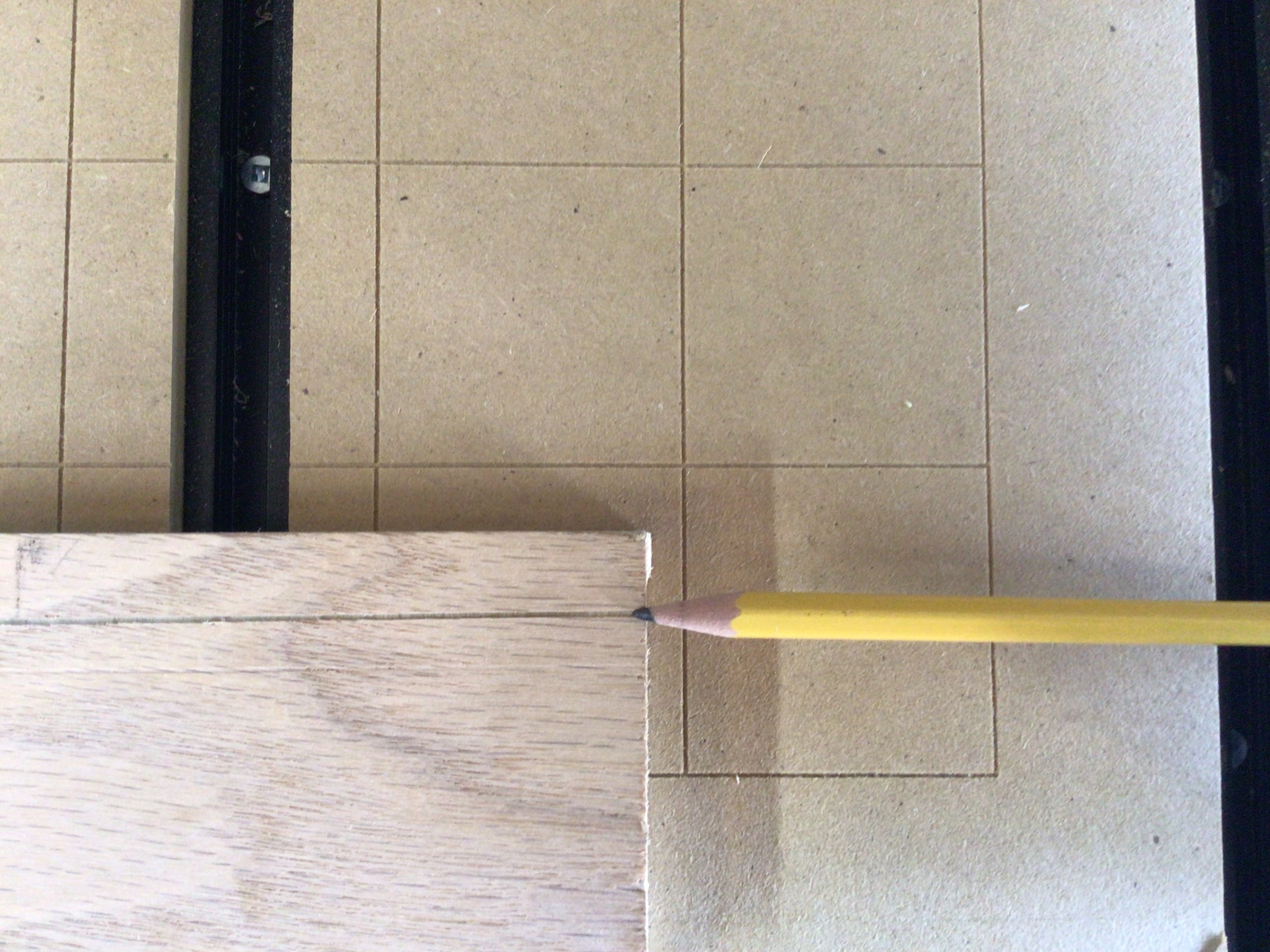
On another note, I cut a line in a board 6 inches off of the front feet and the same board 6 inches off of the rear feet. The front cut was square all the way across the board, at the rear cut it was 11/16 off of the edge on the left (my starting point) on the right end 15/32. The board is 29 inches long and 2 7/8 wide.
I am at a loss at this point, I have tried everything everyone has suggested.
1 Like
@GettingStarted Here is a page showing how the dip switches should be set
There are 4 sets of 4 dip switches - one set for each motor. They should all be set the same.
However, after all that you have been through, if you have not opened a service ticket with Sienci, you should.
Here are the pictures of the cut on the board. The first is the start of the cut and the second is the end.

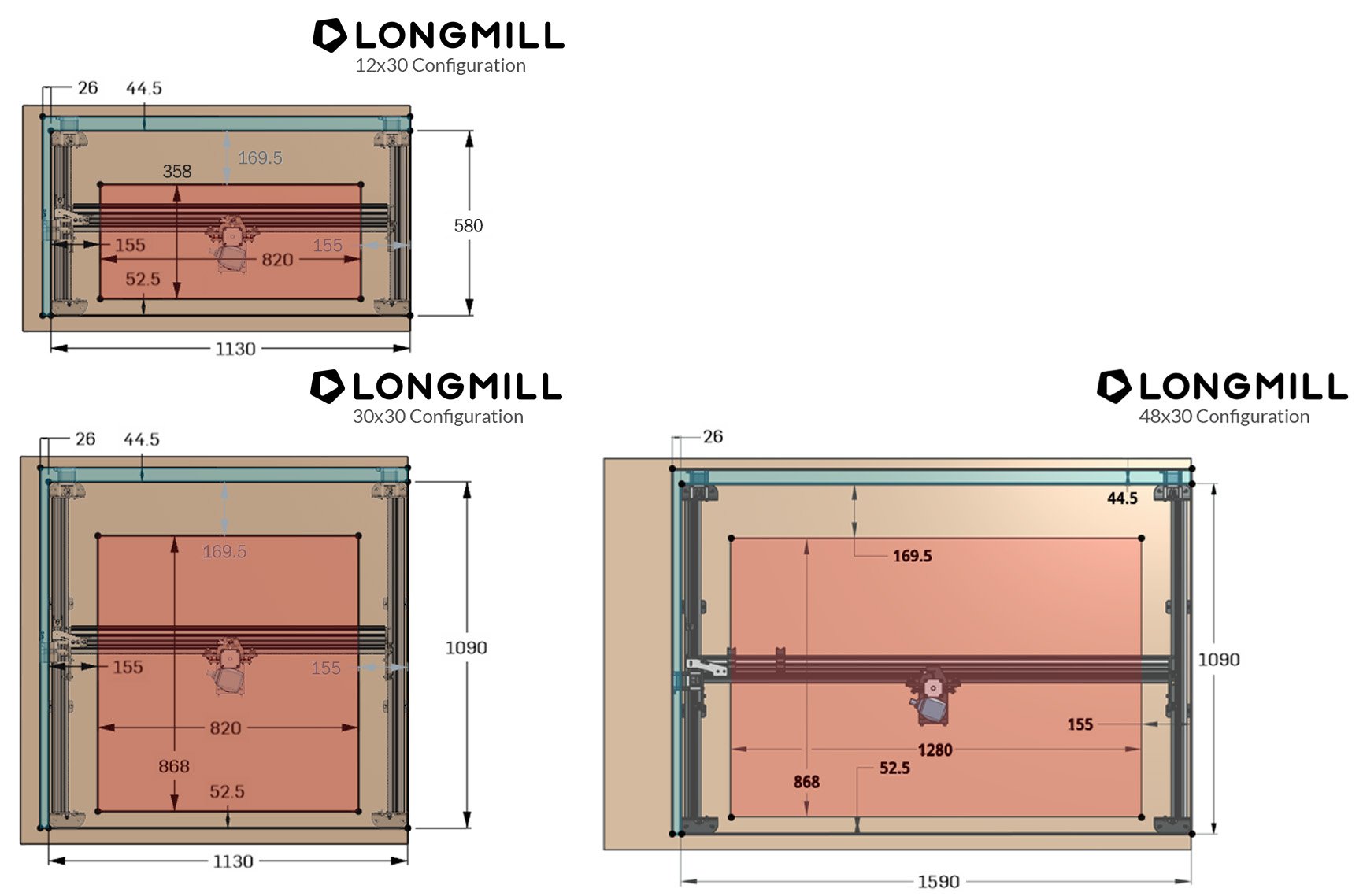
Why do my measurements of the machine not match the dimensions given by Sienci. The overall length of the machine end of foot to end of foot should be 1090mm, I only 902mm? The width is spot on at 1130mm.
I have submitted a ticket regarding the issues I am having with the mill.
Ok, last question for tonight. I just ran diagnostics and my $3 value is at 1 and the default is 5, could this cause any of my issues?

No.
Are you sure the coupler isn’t slipping?
@GettingStarted I’m glad that you opened a ticket.
I’ll add a couple of observations, then shut up while we wait to hear how you get on with Sienci tech support.
-
I had missed your post where you said that switching the Y motor cables did not change anything. That pretty much rules out a dip switch issue. If the switches on one driver were off, the problem would move to the other motor. It still leaves open a motor issue or, as Neil has pointed out, a slipping coupler.
-
I can’t get my head around the test board you posted. I’m assuming the carve is a line running along the X axis. There is no Y axis movement involved at all. To me, that would indicate that the board was not held down parallel to the X movement. Further, if you held it down parallel to the grid lines you carved, the test board would be fine. So, it seems that, after you carved the grid, you changed something. That’s not a criticism, just an observation. Now, then, the grid is no longer an accurate depiction of how your machine is moving. When you line a test board up to the lines of the grid, it will always be off.
3 Likes
UPDATE
I heard from Sienci tech support and they told me to check out a few things, one being the dip switches (he doubted they were wrong) 2nd was to check the anti backlash screws and finally the v wheels. I arrived home and the first thing that I did was tackle the v wheels, the tech Jason wrote that I should support the X axis gantry and adjust the wheels (DONE) I actually switched out the left Y axis lead screw from the X axis and adjusted all lead screws. I adjusted the anti backlash screws last.
I ran the machine front to back and everything was even, I then squared up a board using a laser and measured a 1/2 inch up on the board at 22 inches on the table. I cut a horizontal line and measured the line and it was perfect. I removed the board and did the same, this time I went 1 inch up on the board and set the board at 31 inches and cut the line. The line is perfect, I think I have finally got my machine ready to do some work.
I did not open the Longboard to check the dip switches as this would have been the next step if everything else had failed. Now I have to resurface the spoil board and redo the grid lines.
I want to personally thank everyone that provided feedback and assistance in this matter, you folks are awesome and I am pleased to be a part of this great forum.
Bob
6 Likes