I hope that there is someone out there that can lead me in the right direction, I have spent hours trying to figure out what I am doing wrong. After getting everything up and running the table surfaced and grid lines cut on my waste board, I decided to try my first project of just cutting some MDF for my controller/power supply box.
I lined everything up on the grids, created the tool path in Vcarve Pro and everything was looking great. I pulled the board and noticed that the square was at an angle, top and bottom. The mill is not cutting a straight horizontal line, just to verify I placed another board on the grid lines and cut a shallow straight line with the same results.
I have spent many hours trying to get the X axis parallel with Y and no matter what I try, I cannot get it right. The right end of the cut is longer than the left meaning the left Y axis should come forward or the right back, no matter what adjustment I make both Y axis do not hit the hard stop evenly (if that makes sense) I really hope someone can help me out.
Thank you, yes I used the calibration tool after I completed the machine assembly, when completed it showed that I was off by 0,01 inches I believe. I left it at that and discovered it changed my Y movement so I reset it to default in gSender after getting help on here. I really don’t know what to do, I will wait and see if someone has a solution and once I have it I will have to resurface that spoil board and redo my grid lines.
What causes the Y axis hard stops to not be identical, for the life of me I cannot figure it out.
@GettingStarted Just for clarification, was everything fine when you carved the spoil board grid? If so, then something has changed since then, correct?
@GettingStarted A start may be to make sure that all the dip switches on the control board are set correctly. When doing that, move each switch from one position to the other to make sure that they are completely in the correct position.
If you want to test it before going to that extent, switch the Y cables at the motors and see if the problem moves from one side to the other.
“Update” I played around with the machine again late last night. I unscrewed the machine from the board and started to mount it again from scratch. I used a 4’ T square this time around which showed the machine to be out of square (based on the previous screw hole positions in the board on the left side) After doin this I ran the machine again, there was a minor improvement.
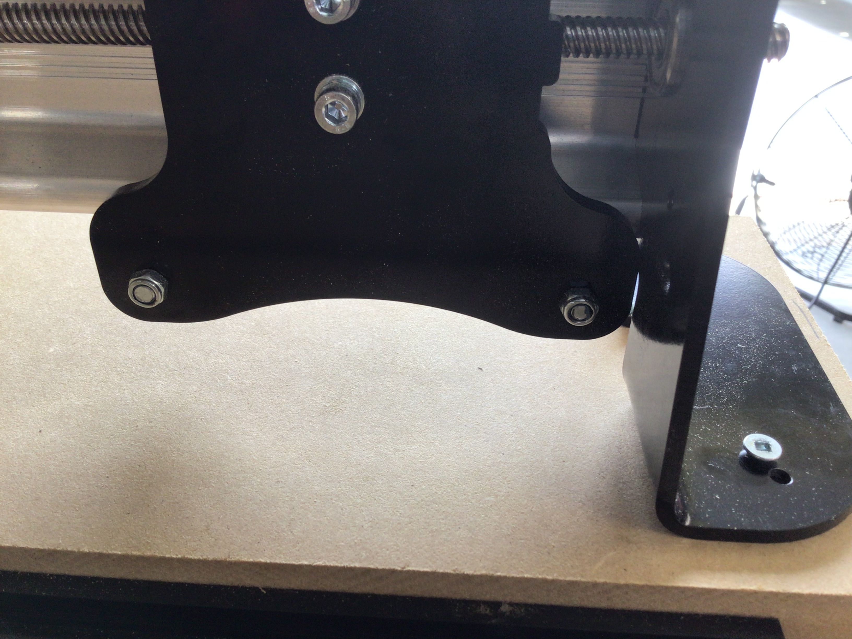
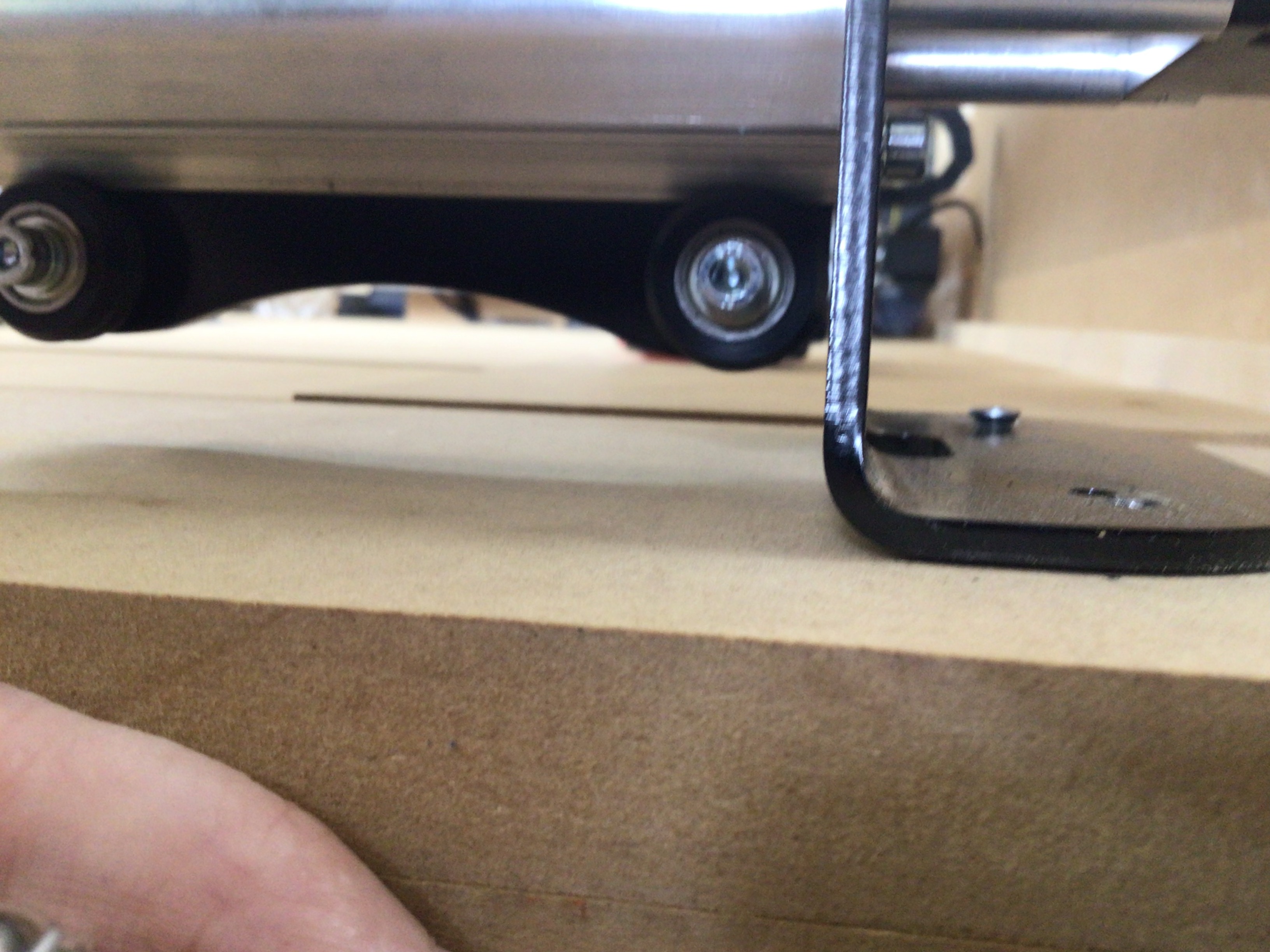
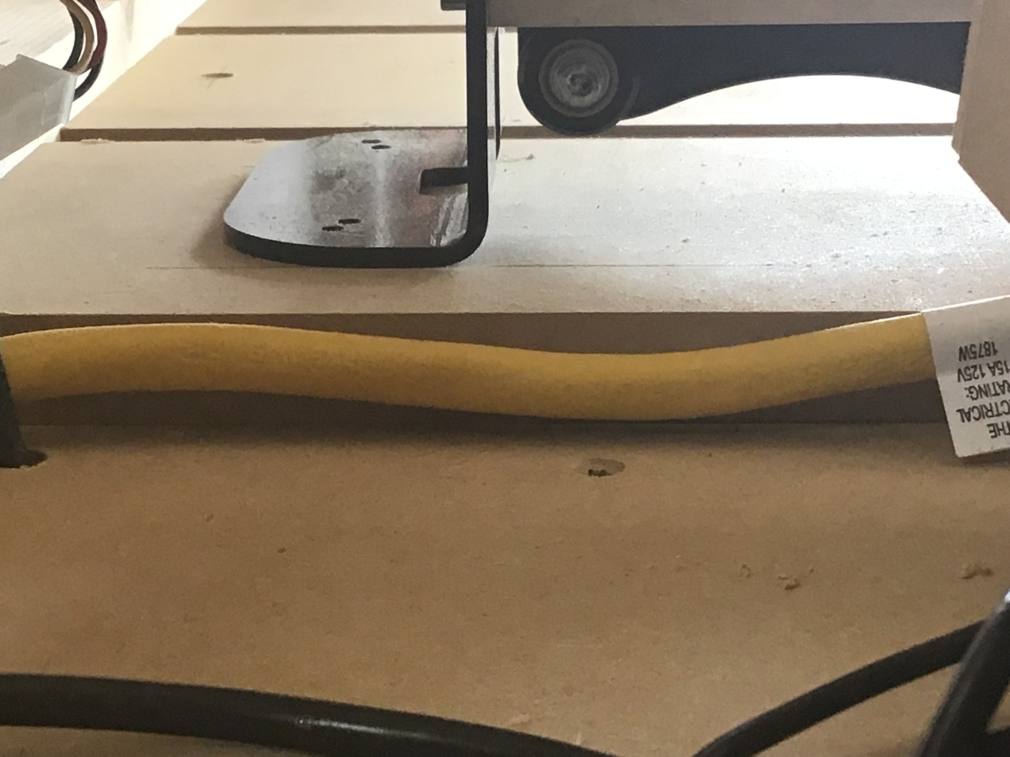
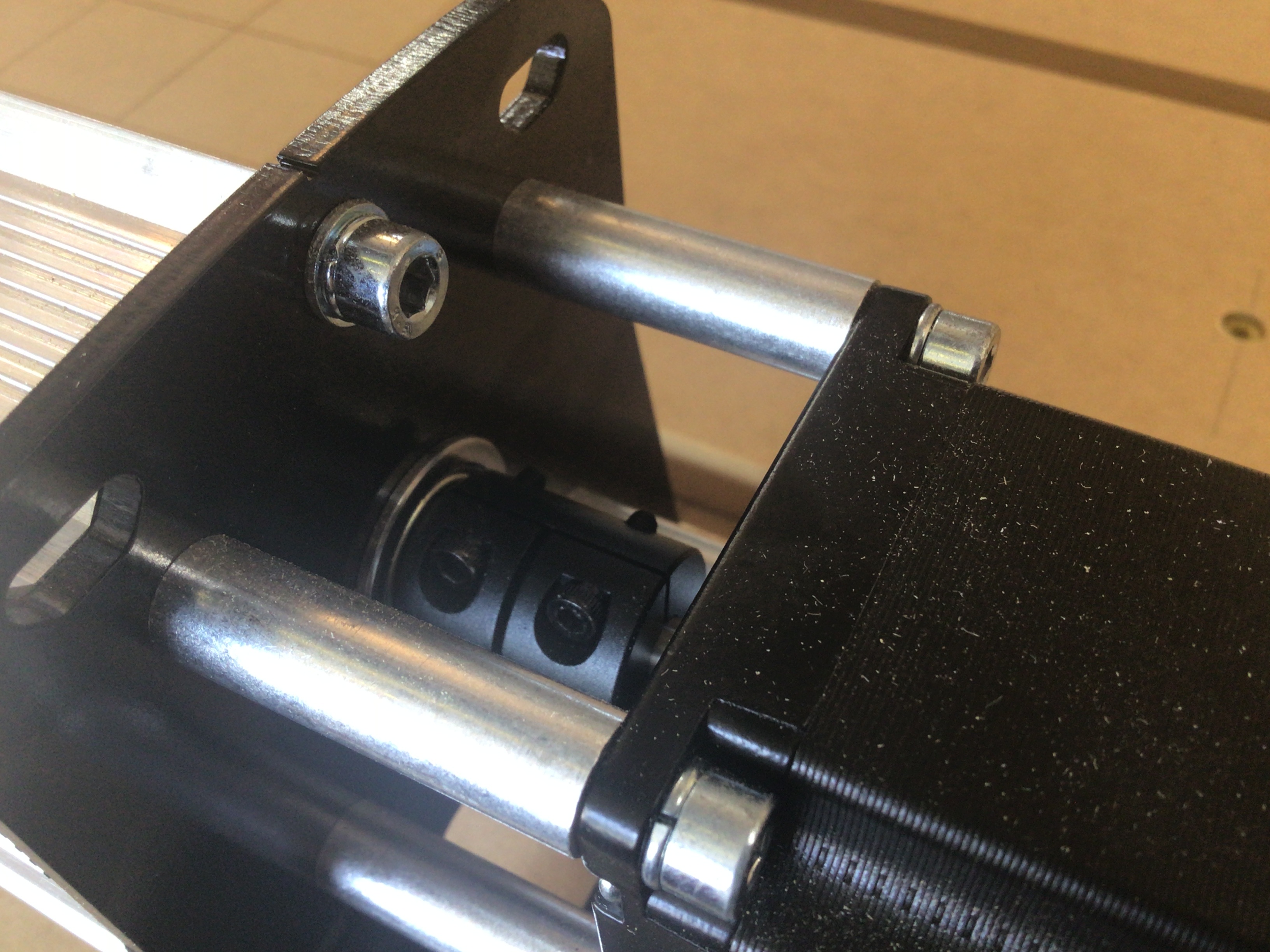
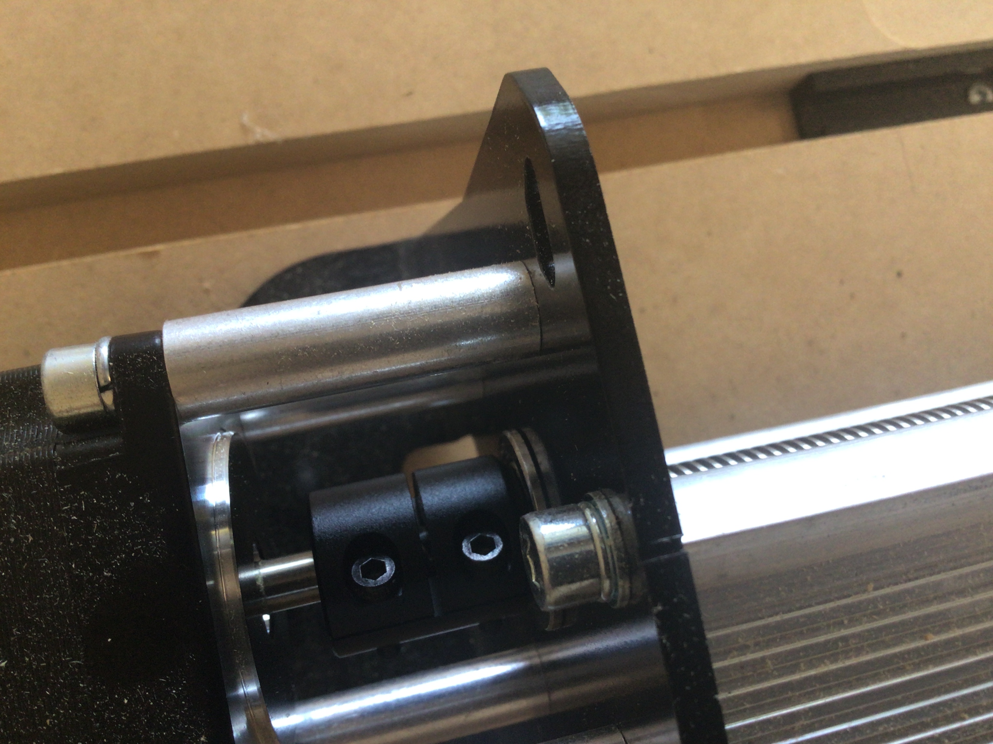
I reviewed other folks squaring issues in the forum and one mentioned to check the lead screws for play, which I did. I noticed that the left “Y” axis lead screw had a lot of play. I noticed that the lead screw was not seated fully into the coupler at the step mother so I readjusted and made sure everything was tight. I ran the X axis forward again to the front feet and they are even, the left rear is still slightly off of the leg in comparison to the right.
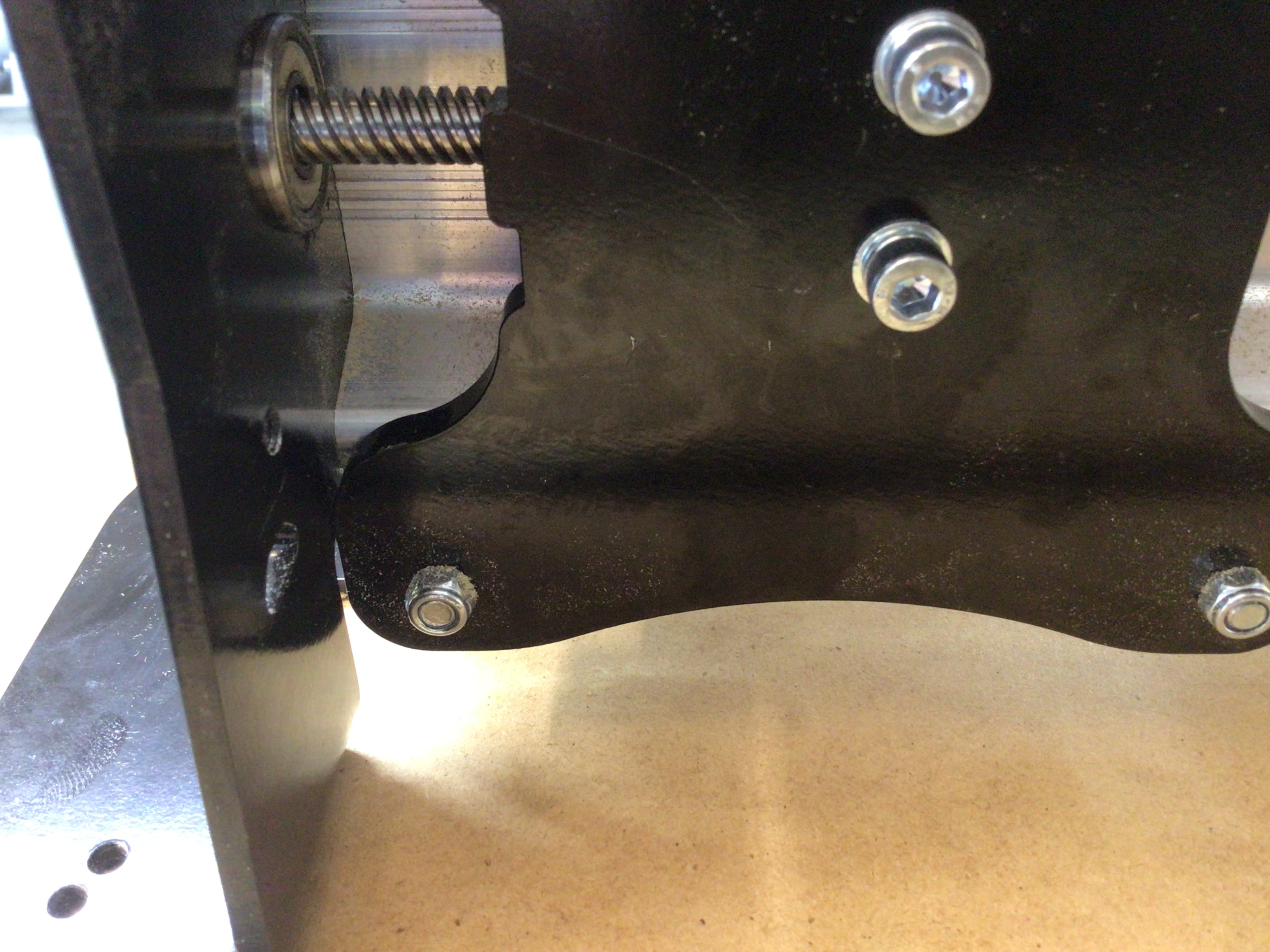
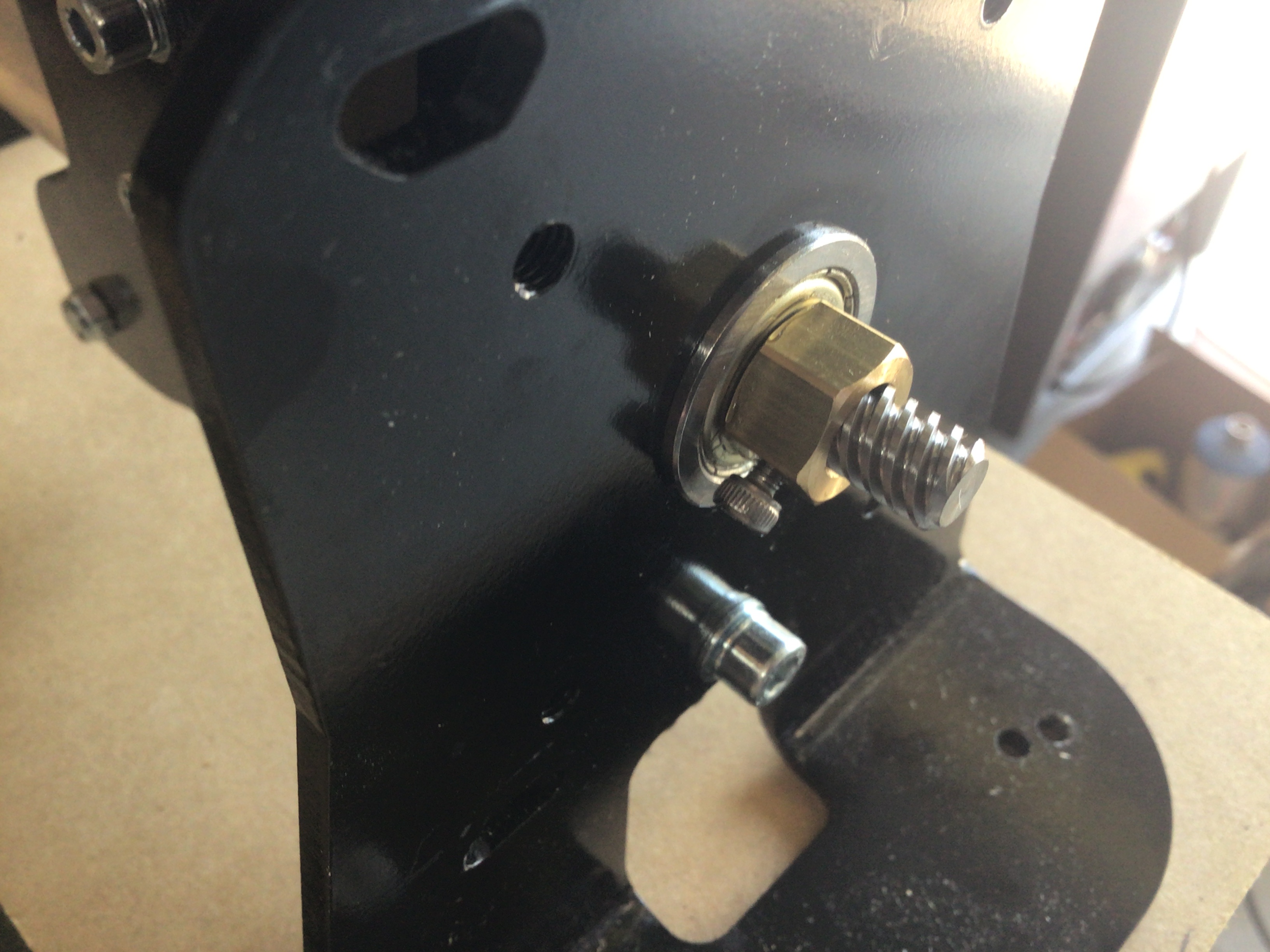
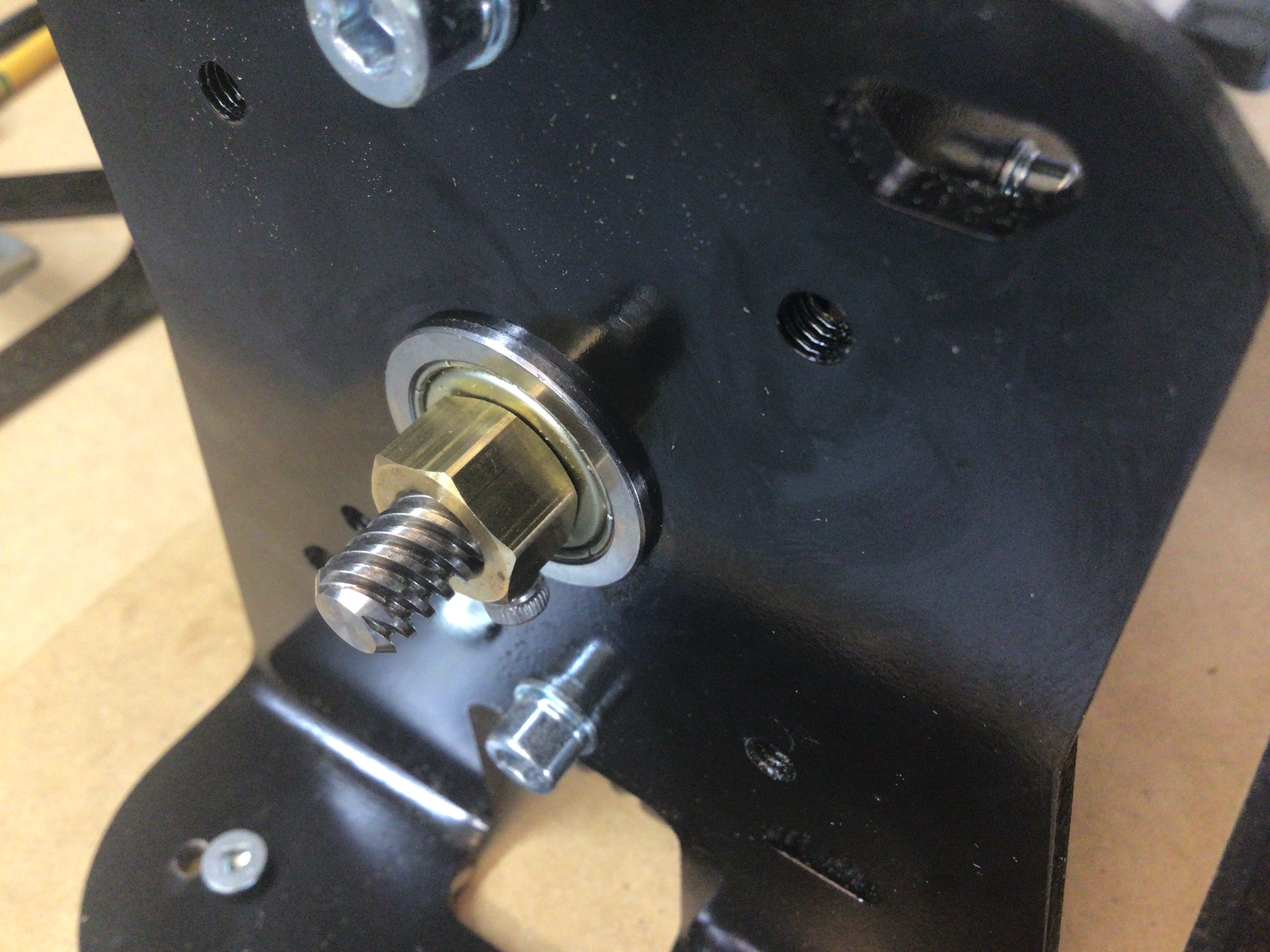
@GettingStarted I may be misreading the pics, but it looks to me like the bearings are in backwards. The flange does on the outside of the plate - the side where the nut is.
No worries, I have been messing around with it since I got home from work and I have moved X all the way forward and the Y gantry’s are both even now. When I send it all the way back the right Y gantry touches first, so the left gantry is of by about 1/8”.