I’d like to introduce Charles to our community. He recently setup an MK2 30x48 at home and built an enclosure for it. He took notes and pics along his journey and wanted to share it with us all.
Thanks Charles!
I’m a CNC hobbyist, with a professional background in 3D printing, materials science, and entrepreneurship. Currently, I am the Business Development Manager at Sienci Labs, and my responsibilities cover making sure the behind-the-scenes of the business run as smoothly as possible.
My house is fairly small, so my LongMill is in my basement, and the general space is shared for other activities. Dust is a big concern, because of the general mess if it gets all over the place, and more importantly, it’s just not good to breathe. I knew I was going to need some kind of cover, so I started by looking over photos of how other people made theirs to get some ideas. I also read a bit how heat can build up for long jobs and this can damage the router, so reducing the noise while allowing heat to escape seemed to be a balancing act for the design.
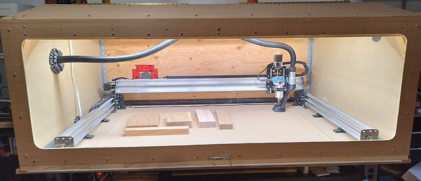
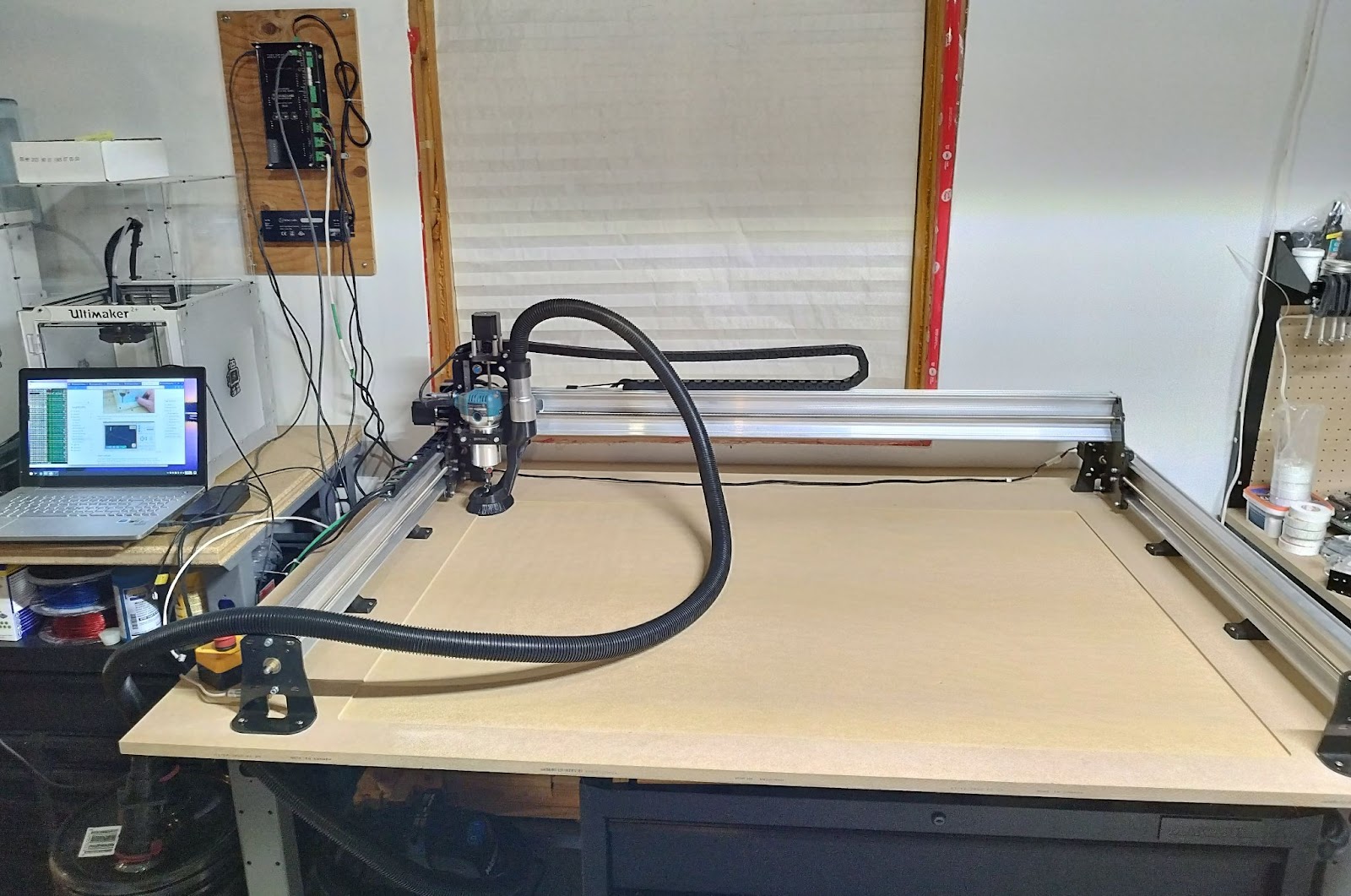
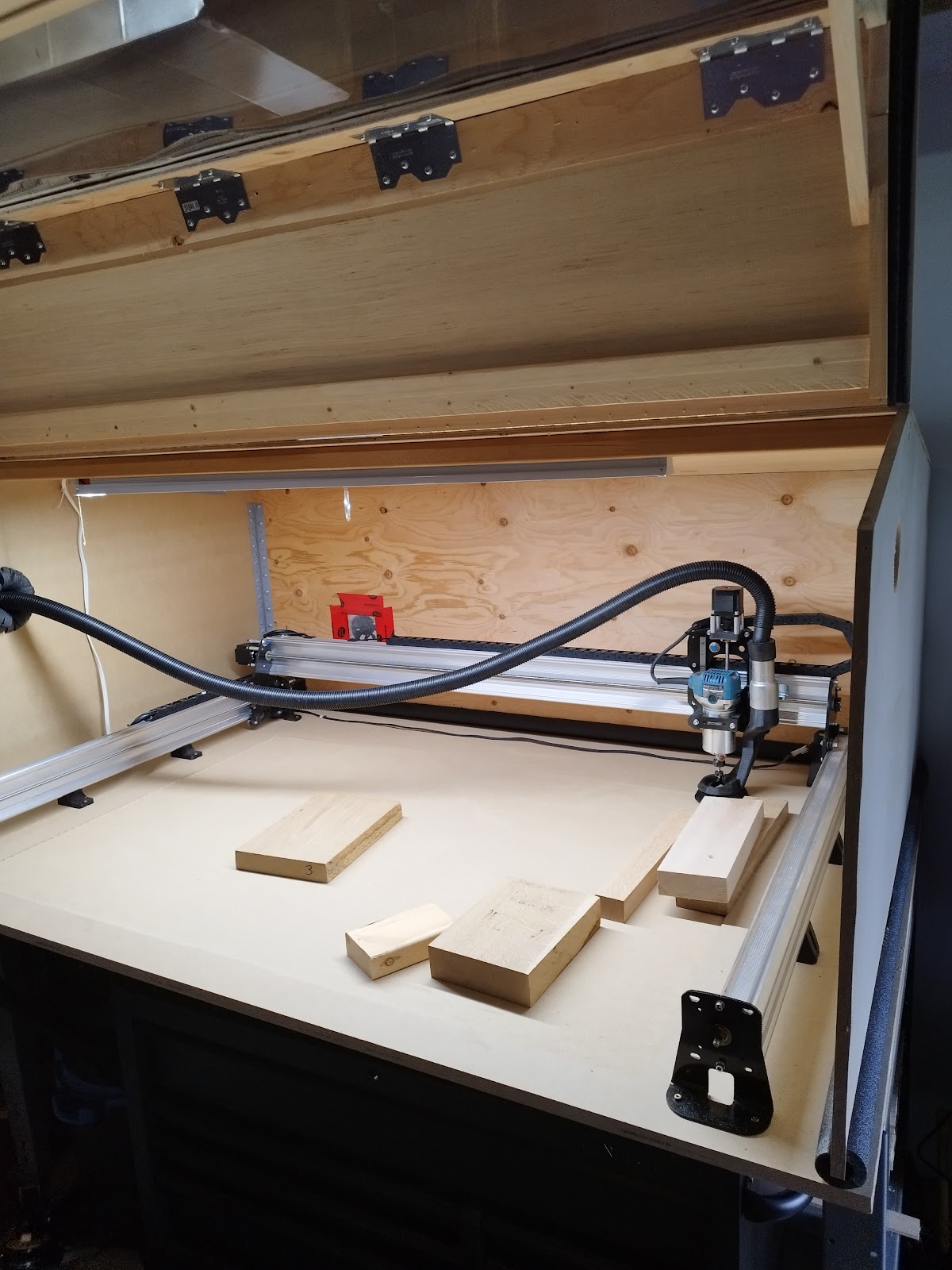
My LongMill is installed on a 4’x8’ MDF spoil board cut down to 4’x6’, which is bolted on top of a sturdy 3’x6’ workbench. I mounted my LongBoard on a piece of plywood fastened to the wall behind and to the side of the LongMill. (I had to make custom extensions for a couple of the cables to make this work.)
I’ll be upfront and say I’m not a very good designer. I have lots of ideas for stuff, and my design methodology usually boils down to a single page of a sketch or two and some measurement notes before I dive into the project. I often find myself making corrections during the build process, but most of the time I end up with a result I’m satisfied with. There have been a few times where this method has failed badly, but I learn new things when this happens and laugh about it later.
Some of my design considerations for this cover were:
- Didn’t want to make the cover super heavy duty and difficult to move (small space, building solo) – but still needed to be sturdy;
- Needed to be somewhat inexpensive to make (budget was around $500);
- Needed holes for air intake and exhaust, and vacuum hose;
- Needed to support vacuum hose with no tangles;
- Needed cut-outs for the cabling;
- Easy lift-up door with a large window.
Other aspects and further implementation clarity on the design considerations came through as I was building through each step.
I wanted the design to have a bit of a raised roof in the middle to make it easier for me to access the back of the work area, so I measured for a comfortable clearance height above the vacuum hose attached to the dust collector and came up with 25 inches. The top of the raised roof seemed better toward the front, so I set that height to be 29 inches, the peak being about 15.5 inches back from the very front. The depth to fully enclose the LongMill was measured to be 48.5 inches (the full depth of the MDF spoil board). The back panel, roof and door sections were all simple rectangles each 70 inches wide.
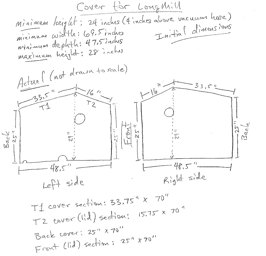
To balance the sturdy and inexpensive requirements, I decided to use ½” MDF for the sidewalls, ⅜” plywood for the back panel and back roof, and ⅛” aspen plywood for the front roof/door. To shorten my work time on this project, and make sure the long cuts were all straight, I had the boards cut to the smaller rectangles at the hardware store. The MDF board was cut to give me two 48” x 29” sections for the sidewalls, and the ⅜” plywood cut to 70” x 25” and 70” x 33.75” sections for the back and the back roof. The thinner aspen plywood was cut to 70” x 15.75” and 70” x 25” for the front roof/door. For the window of the door panel, I found a 1 x 3 meter polycarbonate sheet (1mm thickness) on Amazon for $77 that would do the job.
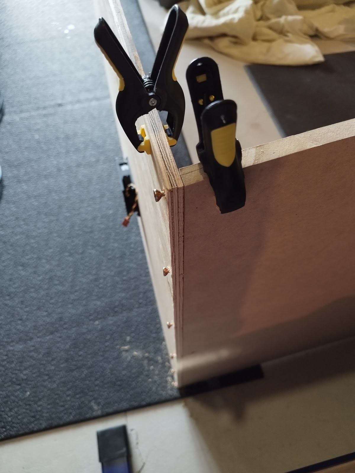
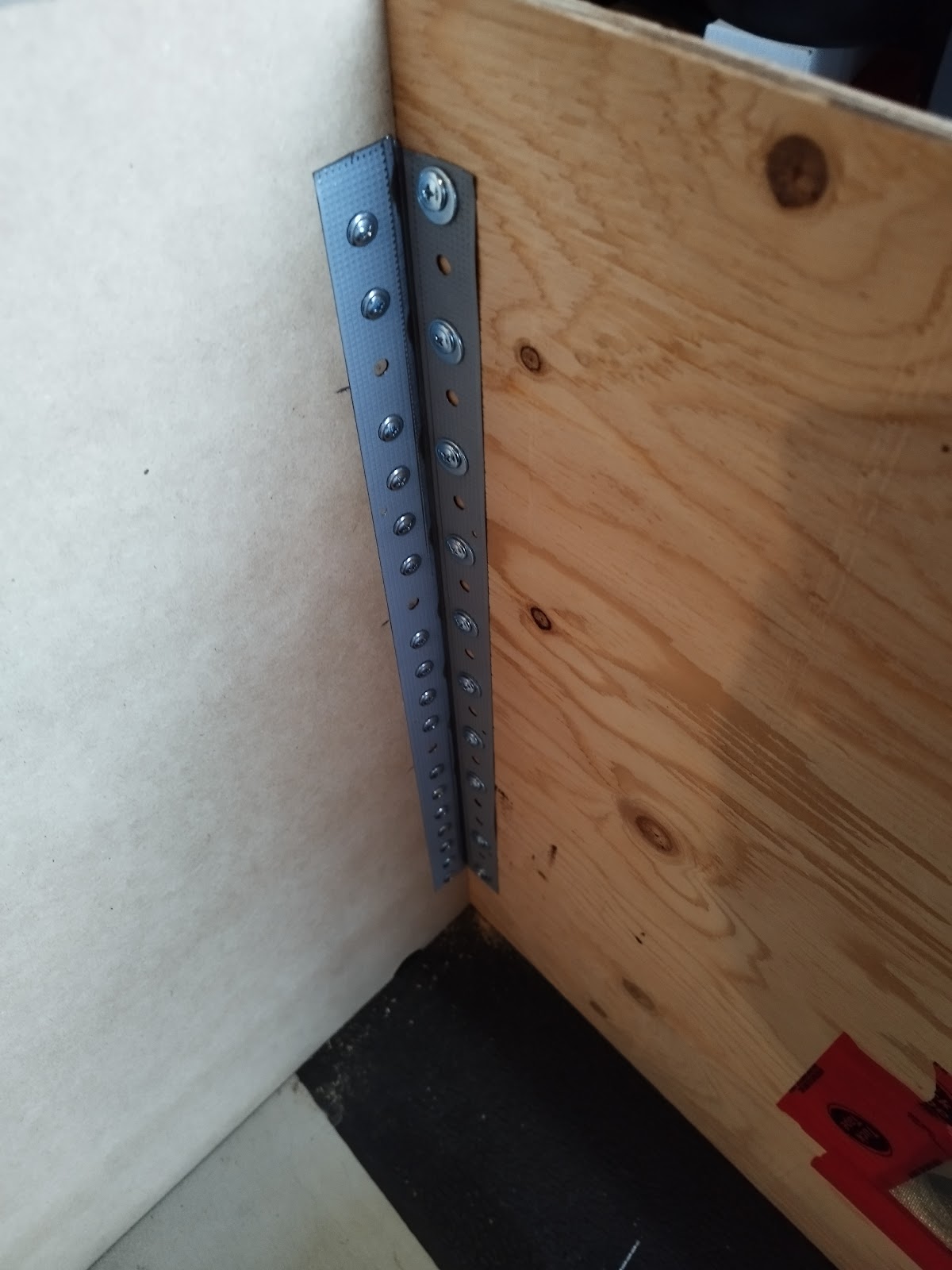
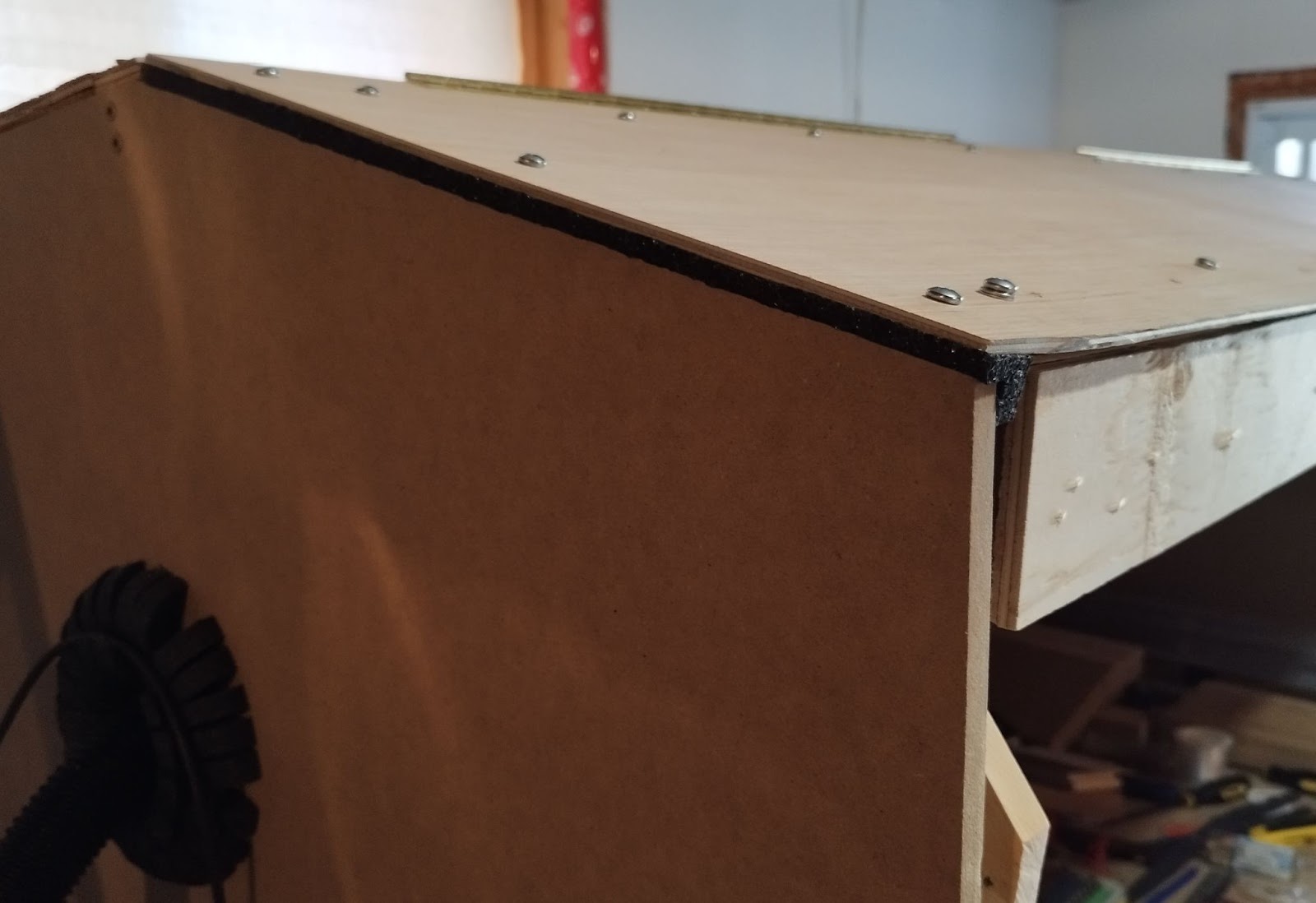
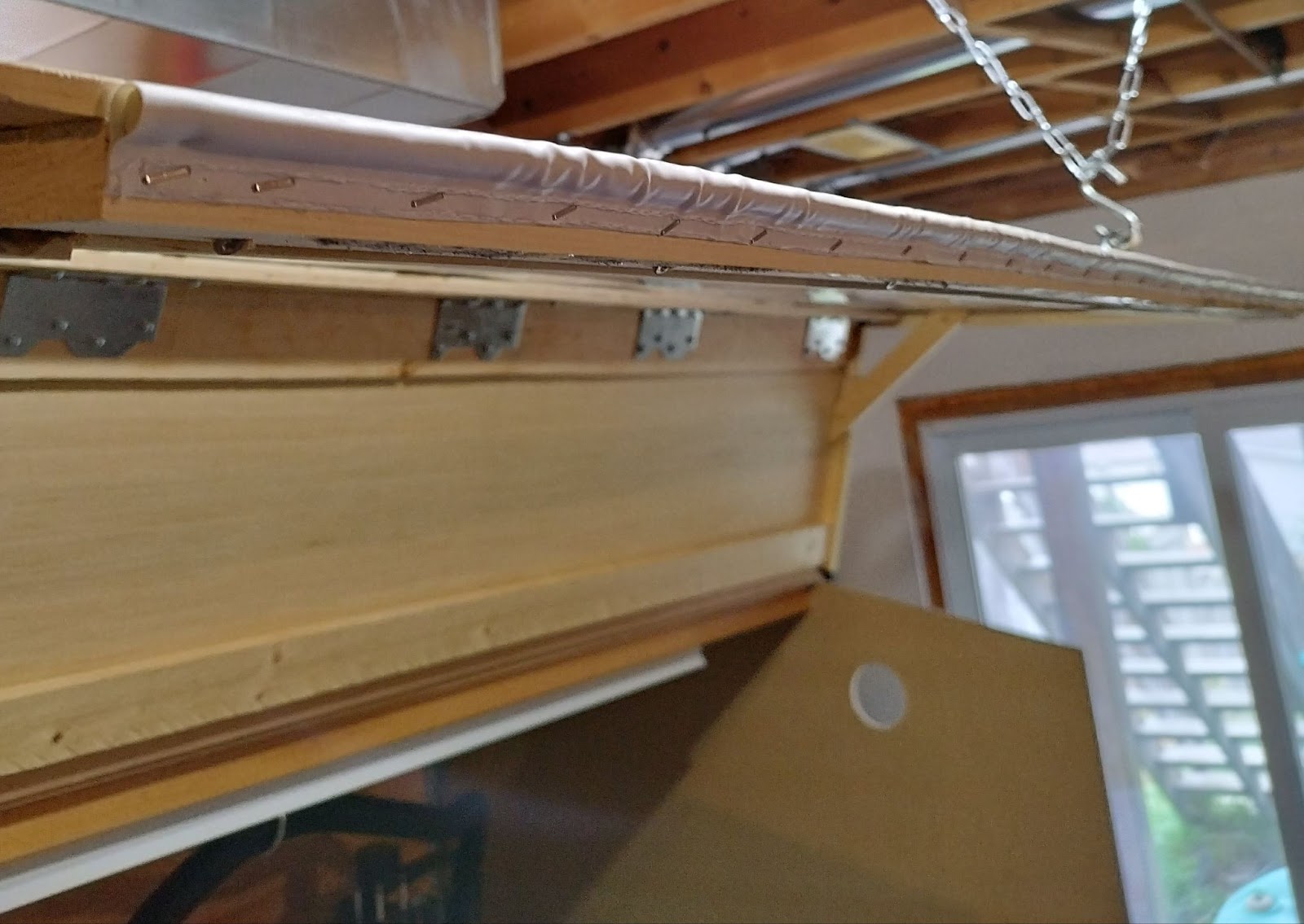
I marked the peak on the MDF boards and drew the triangles to cut off. Then I marked holes for the vents, the vacuum hose, and semi-circle cut-outs for the cables. Once I had all the holes cut, I positioned the boards to join them together. I used screws to fasten the plywood directly into the edges of the MDF, which doesn’t provide a lot of strength (like I said, I make some mistakes, learn, and laugh later). I later reinforced these joints with cut sections of metal drywall corner protectors, but probably a simpler solution would have been to just use a series of plastic corner brackets (), which probably would have been a lot less work.
Once I had the two MDF sidewalls, the plywood back and back roof all joined together, I attached sections of foam pipe insulation tubes to the bottom edge of the structure.
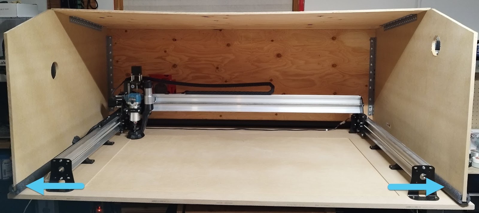
I put the semi-complete cover in place over the LongMill. The top roof panel was sagging a little, so I used a 1”x2” board as a horizontal support beam to eliminate this issue (the 1”x2” was installed with the 2” side facing front/back for optimal support, with long wood screws securing it at each end).
For the cable cut-outs, I scalloped small sections of the foam insulation by cutting a series of lines (each about half the width of the foam insulation). Then I formed the piece inside the cut-out. My intent with the foam was to create some vibration dampening as well as pressure sealing (from the weight of the cover).
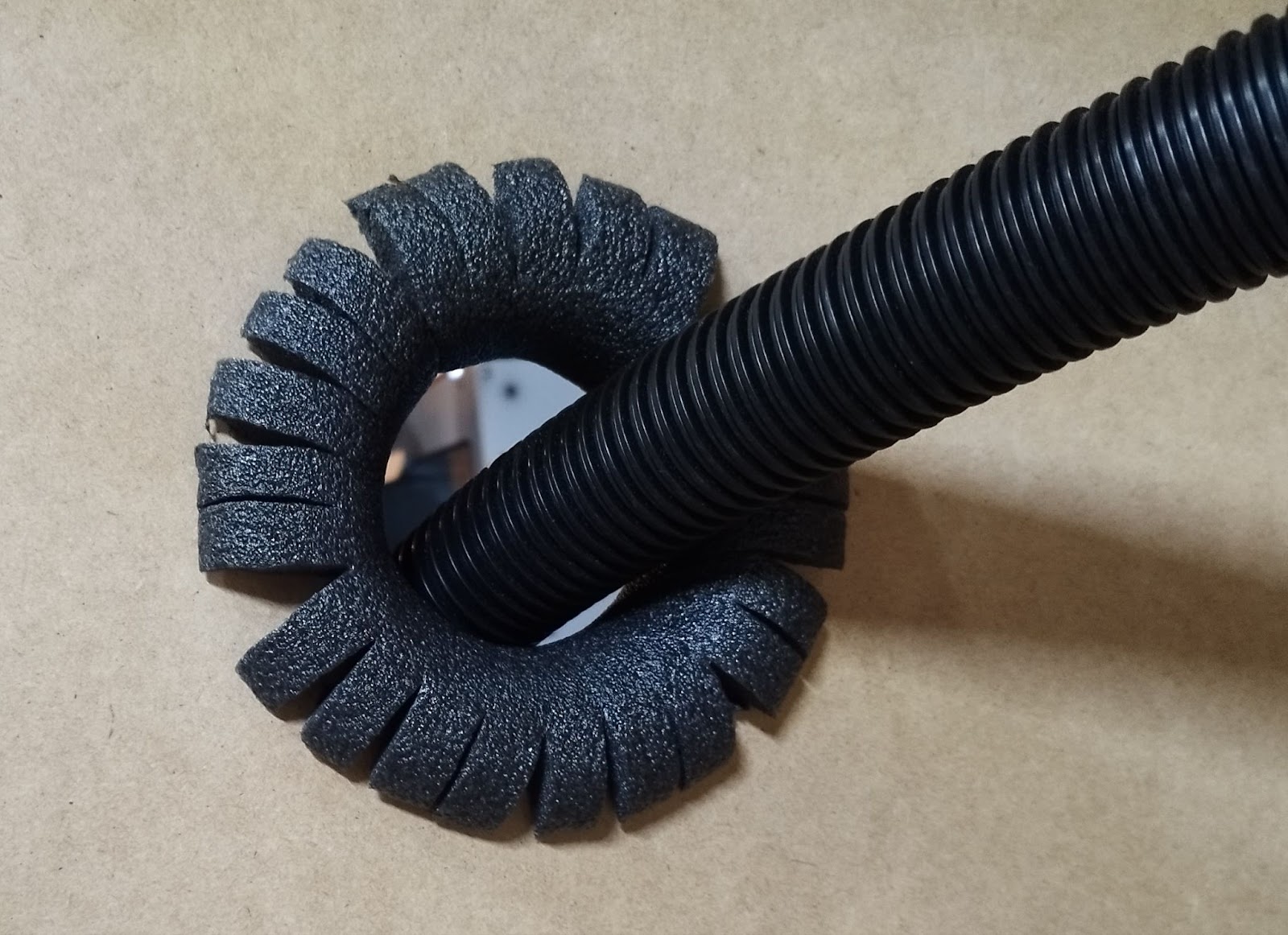
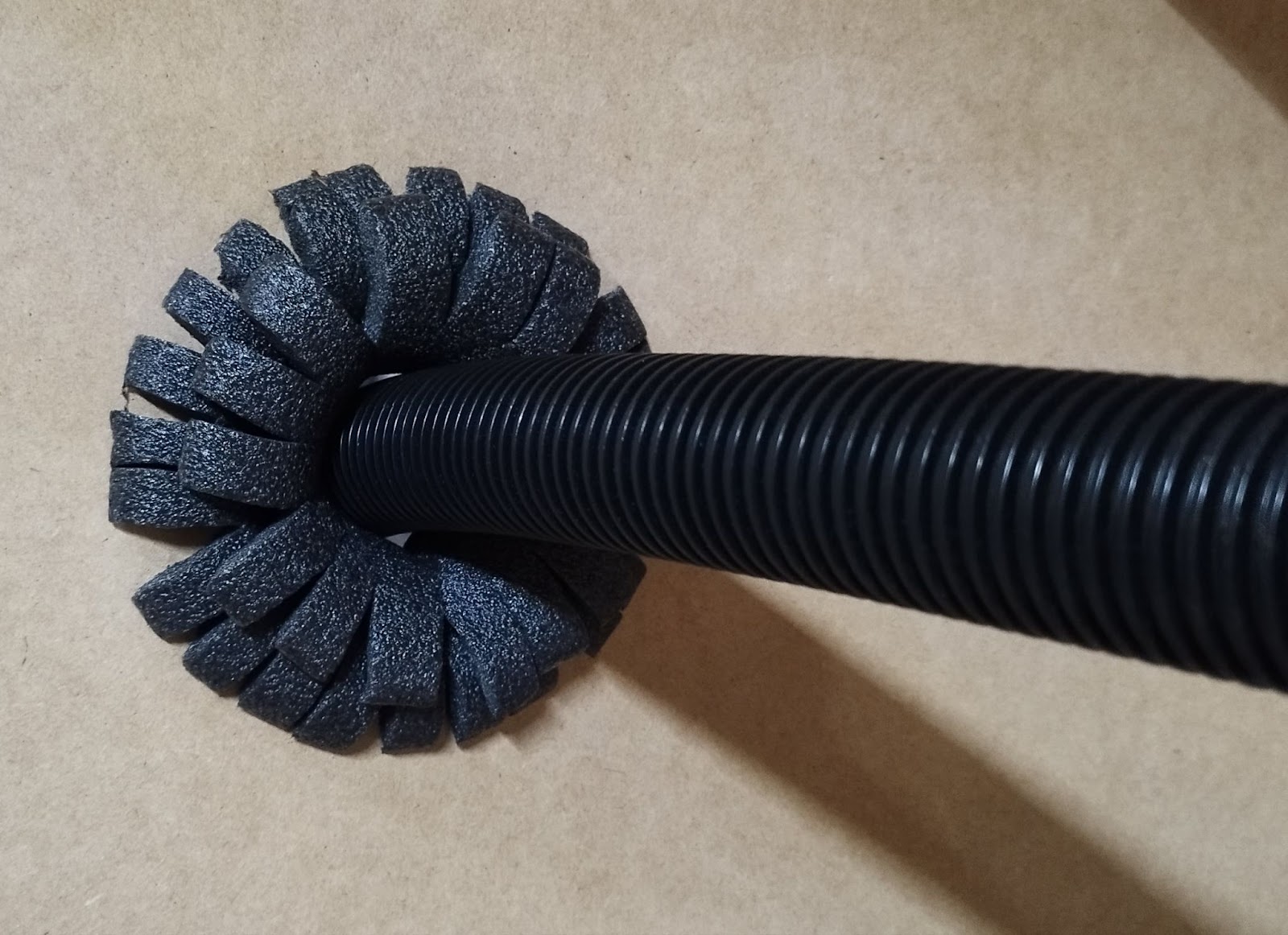
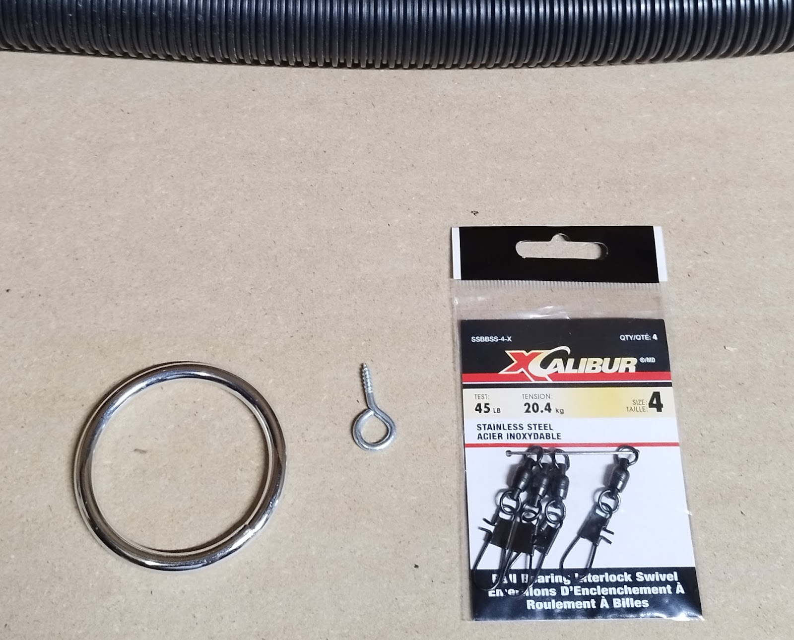
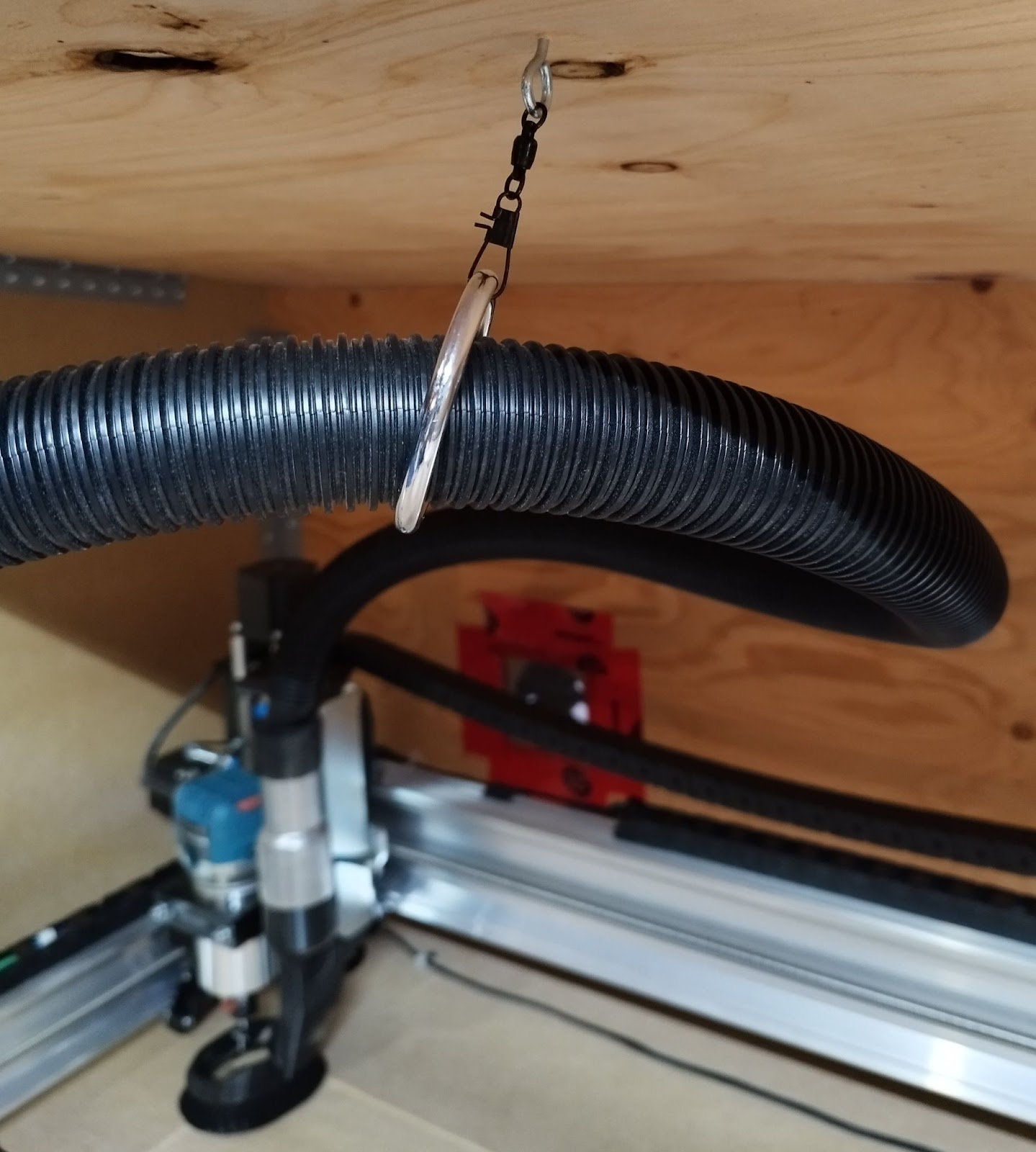
Next, the hole for the vacuum hose needed some kind of smoothness to allow the hose to move as needed, but still not be a leak point for dust. I also needed some kind of way to support the hose inside the cover so it wouldn’t get dragged over projects or get tangled. I used more of the foam pipe insulation for this, cutting lines for a scallop pattern just like I did for the cable cut-outs. I got a better fit here with two layers of foam insulation. My vacuum hose fit perfectly inside, and moves as needed when the LongMill is running. For the inside support mount, I wanted something simple that did the job. I got a small screw with an eyelet, some interlock swivels used for fishing (rated for 45 lbs), and a basic aluminum ring about 2.5 inches in diameter.
I put these together and fastened to the center of the frontward underside of the back roof section, and fed the vacuum hose through. I tested the movement of the LongMill, and the support worked well.
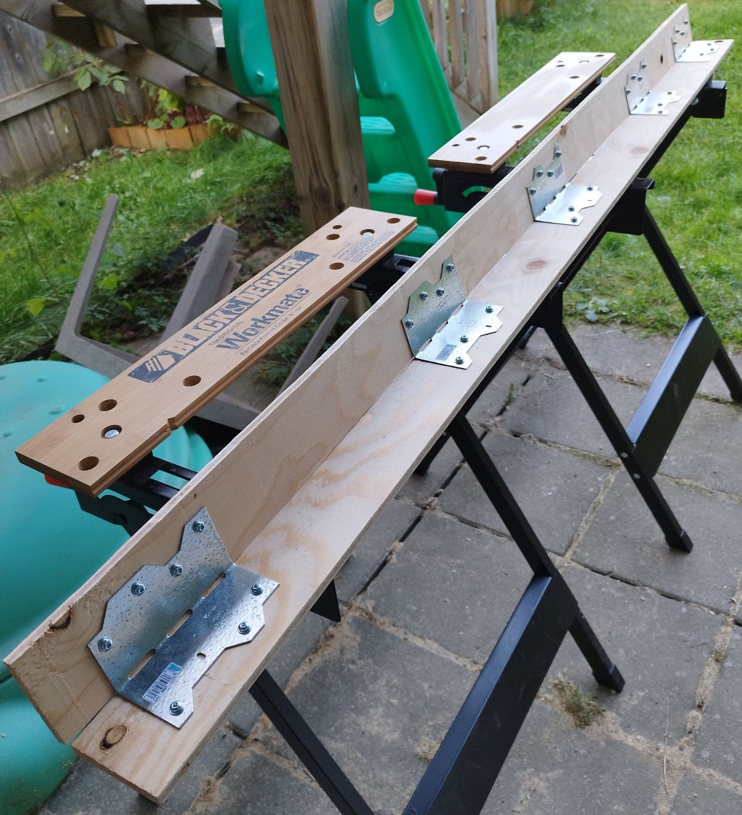
The next section to build was the front roof/door. The aspen plywood looks nice, and is thin and lightweight. However, this makes it more fragile to work with for big stuff. The aspen panels were going to need some support at the stress points. The main support was going to be where the two panels were joined together at an angle to form a single lift-up door. Two 3-inch sections of ⅜” plywood would be sufficient, so I cut a couple of these at 64 inches in length. To connect these two pieces of plywood at the angle I needed, I used some angled fence/deck brackets that had angles of 120 degrees or so, and I just bent them in more until they matched the angle required for my door assembly. I finished connecting the two plywood strips and set that part aside.
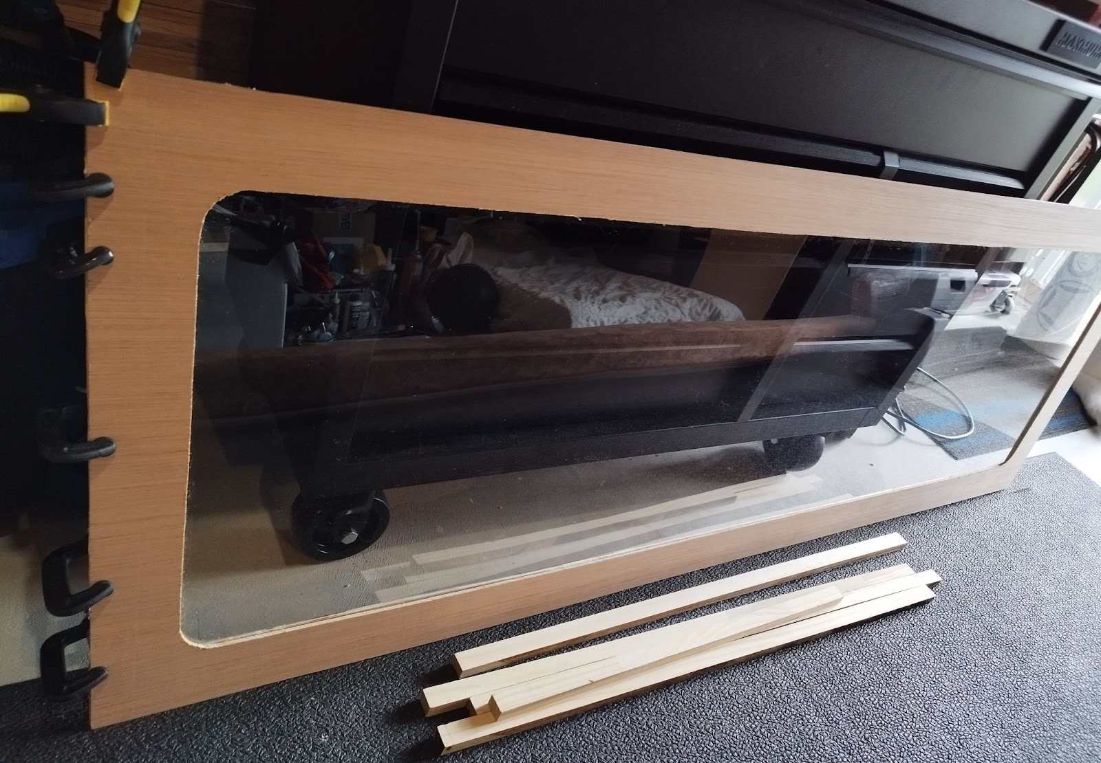
I estimated a 3-inch wide perimeter for the 70”x25” piece would be sufficient structurally for the window. I drew rounded corners for a better look, then cut the window section out with a fine-tooth saw. I used some of the scrap parts of the aspen plywood to cut 3” strips for the backing. Using some shears, I cut the polycarbonate sheet to size, leaving a gap roughly 1” inside the perimeter of the window frame. Next, I positioned the polycarbonate sheet flat on to the window frame, and glued the backing pieces so as to sandwich the sheet, like a large picture in a frame. I used a bunch of weighted objects to apply pressure for 24 hours until the glue dried.
After the window panel was ready, I attached the angled plywood strips to one end of the inside of the window panel. For the front roof panel, I glued a scrap length of aspen plywood to one lengthwise side for reinforcement later when attaching the piano hinge. Once that glue dried, I attached the front roof panel to the other side of the angled plywood piece. To finish out the structural support of the overall door piece, I used some 1”x1” scraps I had and fastened sections of these to form a frame around the inside perimeter of each panel (except the joint with the angled plywood), leaving a gap of about 1.5” from the outermost edge. Now the full door fixture was done and ready to connect to the rest of the cover assembly.
Once I tried attaching the door fixture to the rest of the cover assembly, I realized pre-assembly of the full door piece was a mistake. It didn’t quite fit correctly, and I was going to have to do some adjustments. So I removed the window frame from the door assembly, leaving the angled plywood strips and side braces on the front roof panel.
The roof panel wasn’t quite up high enough to allow for the piano hinges to be attached properly, but the rest of this piece fit properly. I figured the door would need some foam around the edges to help it seal well when using the LongMill, so I cut some strips of packaging foam I had laying around and placed them under the edges of the front roof panel. Now, it was level with the other roof panel, and I could install the piano hinges. The hinge installation went smoothly, and the movement of the roof portion of the door worked the way I wanted. I then glued the strips of foam in place. Now, on to the window panel.
Here’s where I discovered my next mistake. The angled plywood strips were sticking out too far, which was going to make the window panel hang off the edge of the spoil board. Thankfully, this could be solved by some repositioning of the angled plywood strips, so I unscrewed that part, repositioned it, drilled some new holes, and got the alignment better. I positioned the window panel to attach it, and everything lined up very evenly – except the bottom, which was 1.25” above the spoil board. Sigh.
I realized the gap was introduced by the foam pipe insulation under the whole cover, as well as the foam strips under the edges of the roof panel of the door. I didn’t calculate for that in my quick design. The window panel came out nice, and the cover as a whole went together pretty well, so I didn’t feel like I needed to redo it. I went ahead and secured it to the angled plywood strips, and resecured the side braces.
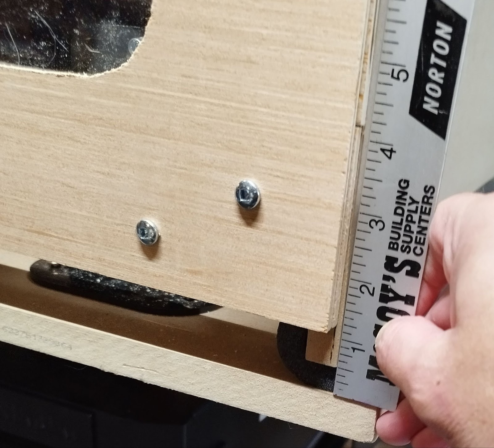
Now, how to resolve the 1.25” gap under the window panel. I did some measuring with some of the scrap wood I had laying around, and it turned out the gap between the inside support frame and the spoil board was an exact fit for a 1”x2” on the 2” side. And the front-facing gap could be cleaned up aesthetically with a simple bit of 1” plywood trim. Done. I purchased these boards and cut them to length. I attached the 1”x2” section with screws and wood glue for reinforcement, and the 1” plywood trim with just wood glue. The result looked decent, and the only gap remaining was about ⅛” in the center area, purely due to deviations in my MDF spoil board.
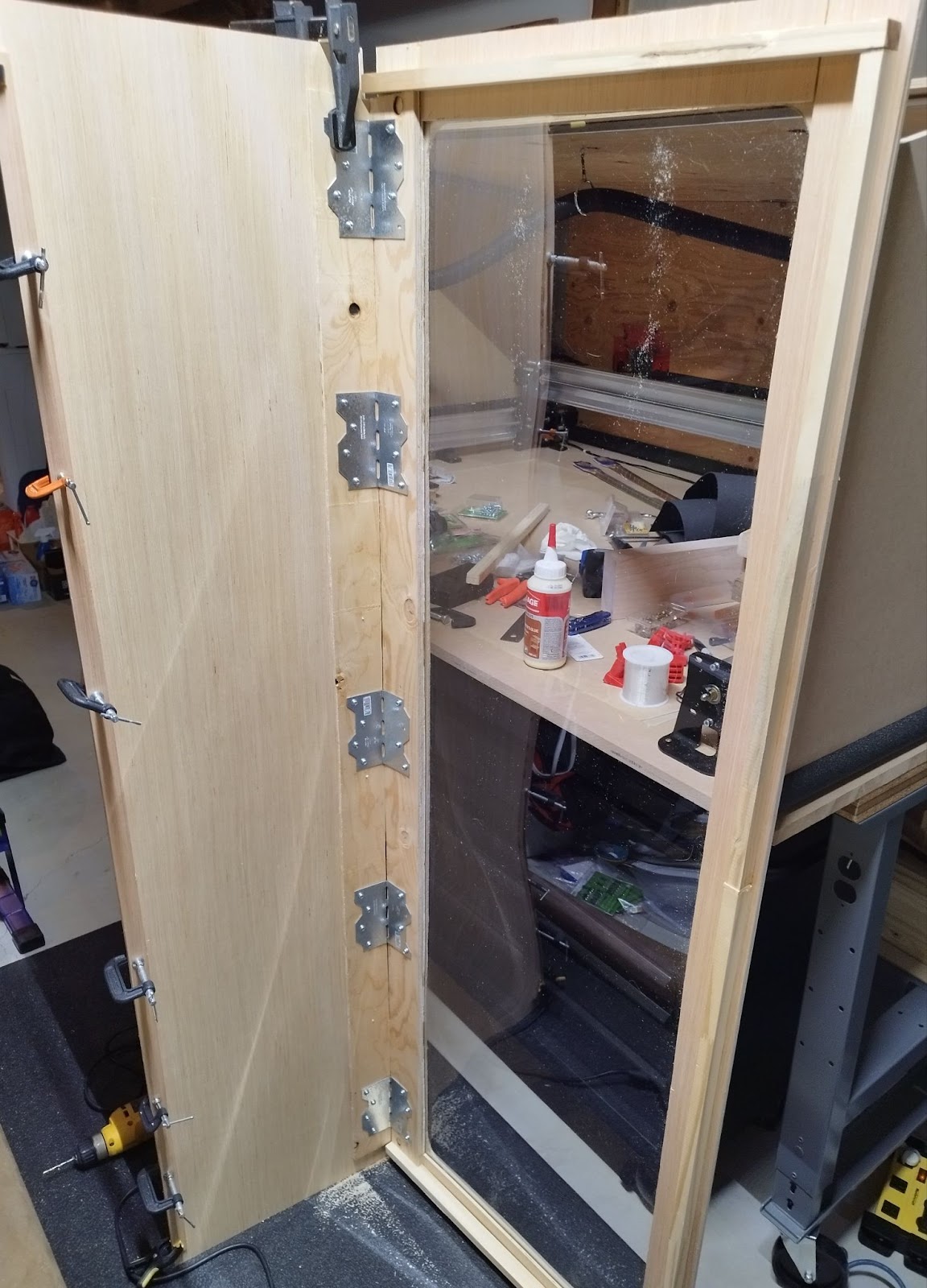
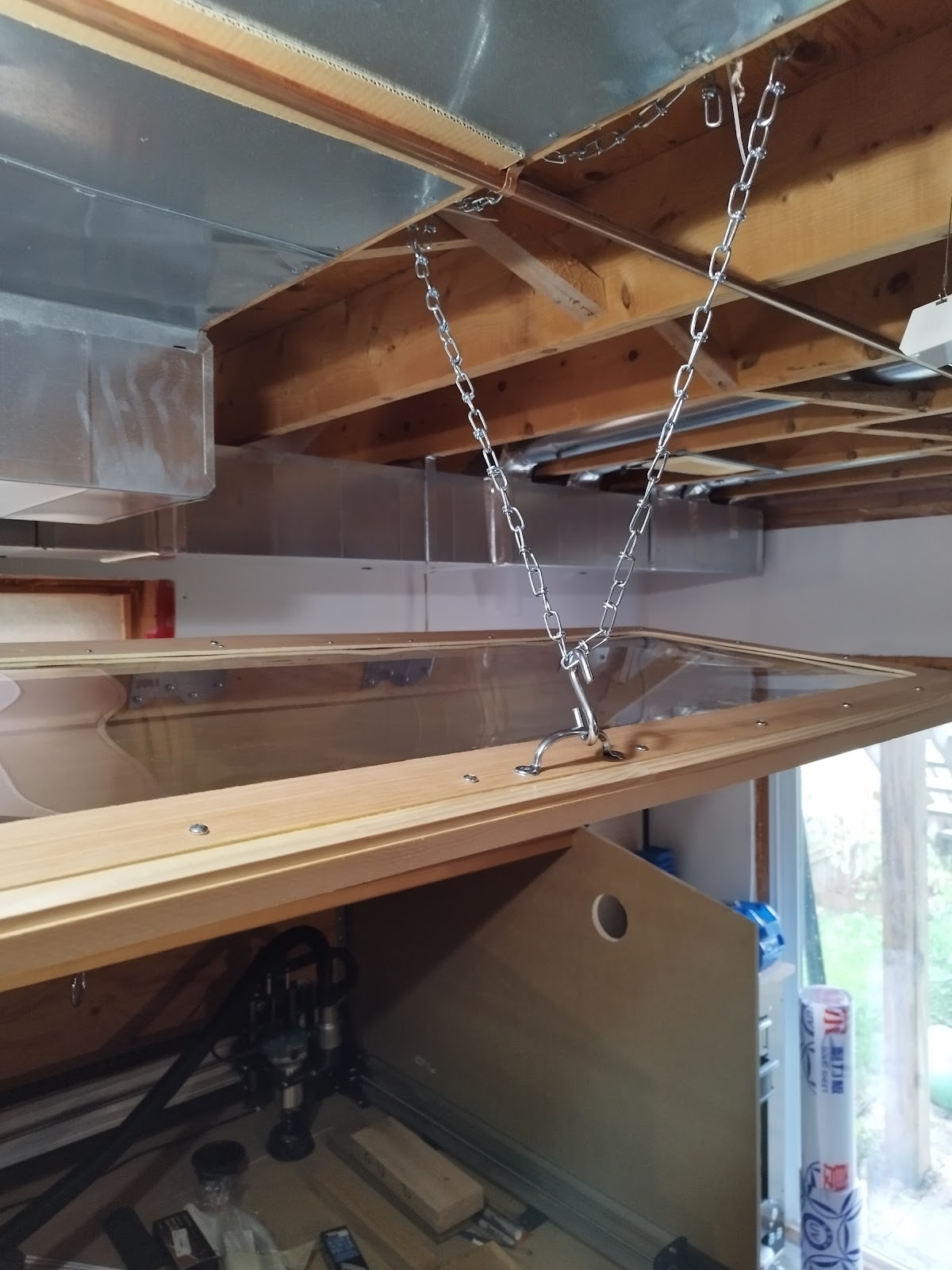
I attached a simple handle to the bottom of the window panel for lifting. To hold the cover up when I need to access the inside, I installed a chain with an S hook in the ceiling beams in my basement. Being able to hold the cover up was also helpful for finishing the final trim.
It seemed simple enough here to just cut some foam to seal that small gap. After a couple of failed attempts with foam, I decided to take a different approach. The problem with the foam was it was very hard to get the custom contour to fully seal the gap all the way across. After thinking about this a bit, a better approach seemed to be to add some door weatherstripping to the bottom edge of the window panel.
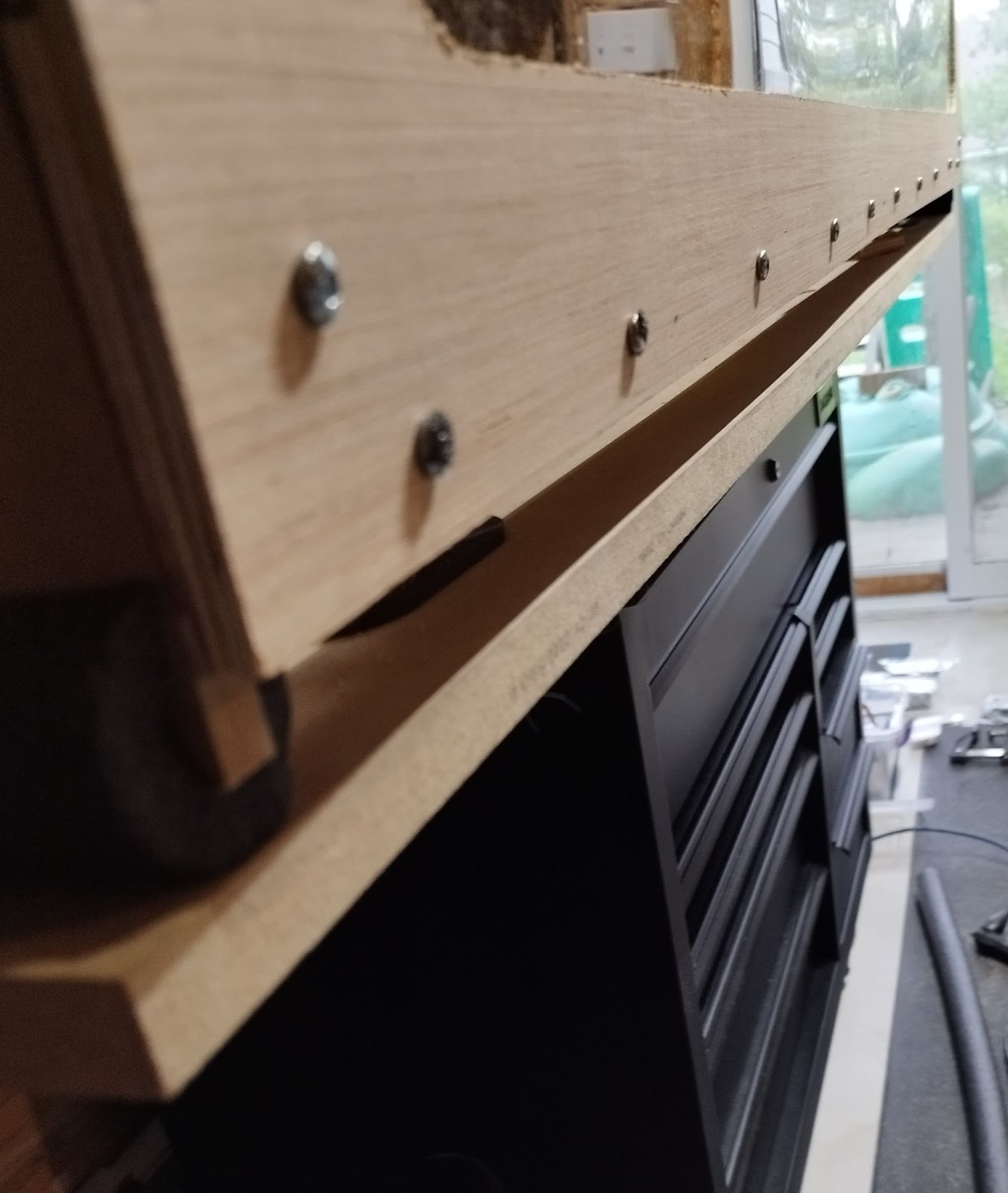
To make sure the bottom was even for the weatherstripping, I used some 60 grit sandpaper and my power sander. This made quick work of the glue and foam I had previously tried, and resulted in an even surface for the final trim. The weatherstripping I used consisted of a round foam extrusion covered in a vinyl sleeve. I simply stapled the vinyl sleeve to the bottom of the window panel, and it filled the remaining gap well.
Next, I added some lighting, since I want to be able to see what’s going on when I’m running the LongMill. I was going to use some LED strips since they would be very lightweight and take up almost no space. However, it seems the lifespan on LED strips is not that great, along with a bunch of other included features I don’t really need or want. Instead, I bought a low profile LED shop light that was fully enclosed for around $20, and a separate inline on/off switch for the plug that would let me turn the shop light on/off outside of the LongMill cover.
Although I didn’t build this cover specifically for noise dampening purposes, I was curious if it had any effect on noise levels. Using a sound meter app on my phone, I measured the noise with the router running (the LongMill being stationary) at about 70 dB when the door was open. With the door shut, the noise reduced to about 65 dB, so there is some slight noise dampening. I’m sure I could reduce the noise further with some foam tiles or similar materials, but it’s not a huge issue for me at the moment.
In the end, I came out spending around $700 – a little over budget (and not including a decent ventilation fan), but I’m happy with how everything turned out, and I definitely learned some lessons and had some laughs along the way.