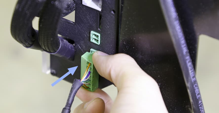
I had to remove the 7 pin plug for the e-stop to route the wire for my CNC but now I’m unsure as to the correct wiring.
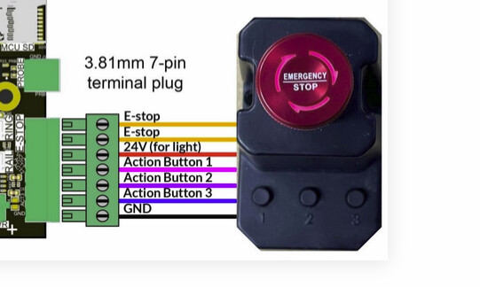
the diagram for the superlongboard (Estop)doesnt match the cable colours. The cable appears to be a standard cat5/6 Ethernet cable.
I cant find a schematic for the estop or the RJ45? end of the wiring
does anyone have, or know the location, of either the e-stop schematic or the pin order of the RJ-45? to match the Superlongboard schematic (1-7)(GND,A3,A2,A1,24V,Estop,Estop)?
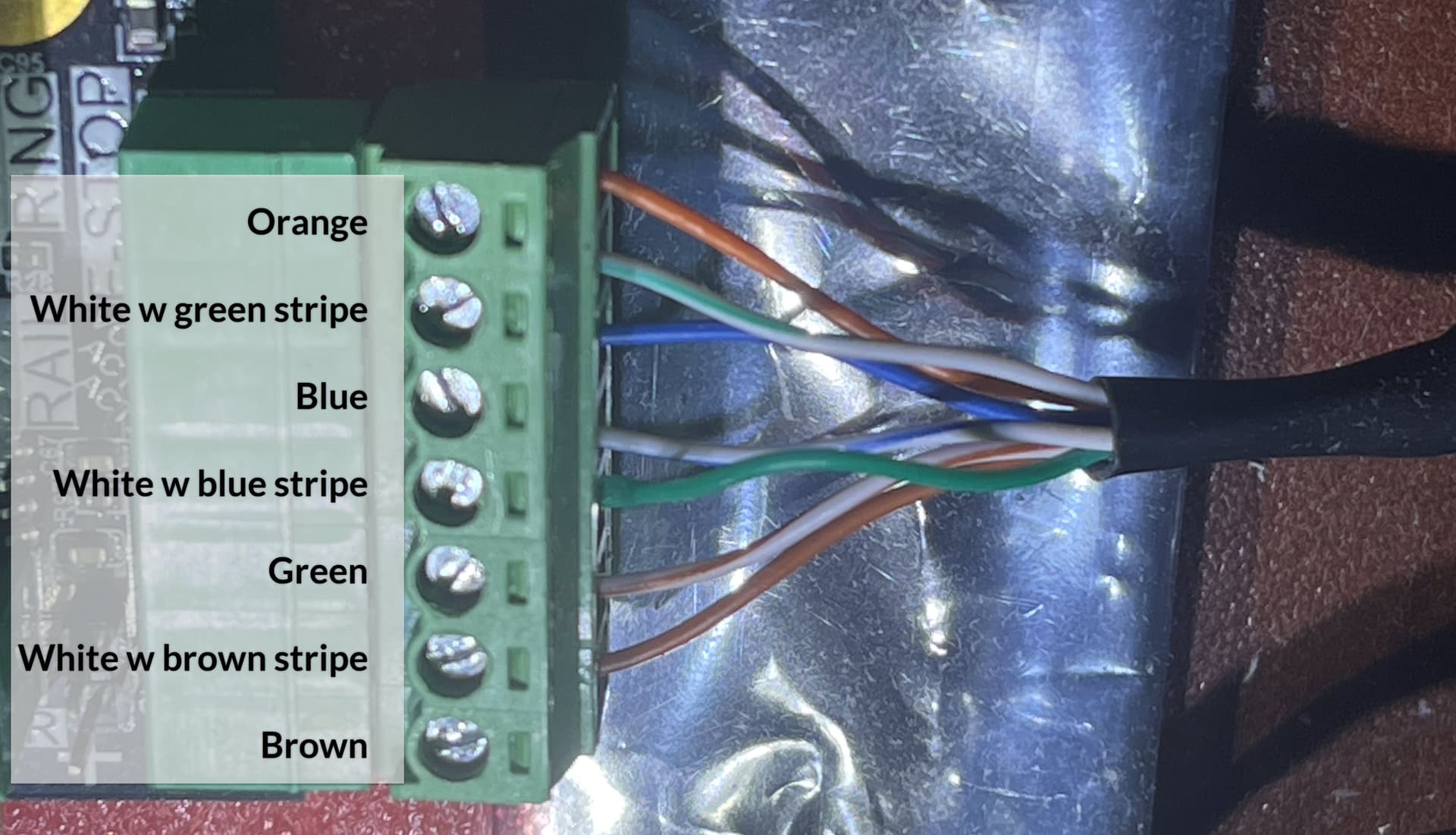
IT’s not much but it might juuuuust be enough to get ya going.
If you do have a universal measuring device, you should be able to sort things out just by measuring the wires while disconnected from the slb using these diagrams and schematics.
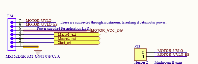
Whit the estop disengaged, you should be able to find Motor UVLO and MOTOR UVLO ES. They measure zero when measuring ohms. To make sure you have the right wir\es. Engage the e-stop button. Your measurement should drop away.
These wires are not polarity sensitive, they just go at pins 6 and 7.
The small buttons on the e-stop will short to ground when pressed. Just press one and measure ground (brown?) to the other wires one after the other untill you measure zero ohms (shorted). Release the button to see if the short disapears and you have the wire corresponding to the button you pressed and know where it goes.
You can measure all wires untill you have one left. That one will go in 5.
Disclaimer: I do not own an SLB e-stop so this is all theory at best. If any measurements seem off, stop and disregard my post. It’s pretty darn important that the right wire ends up at pin 5. When in doubt, better open a ticket and have real siencitists help you out.