Finally made my first cut (and first oopsie) with my Altmill

I had some difficulty getting up and running, but as of 15 minutes ago I have a functioning CNC machine!

The specs

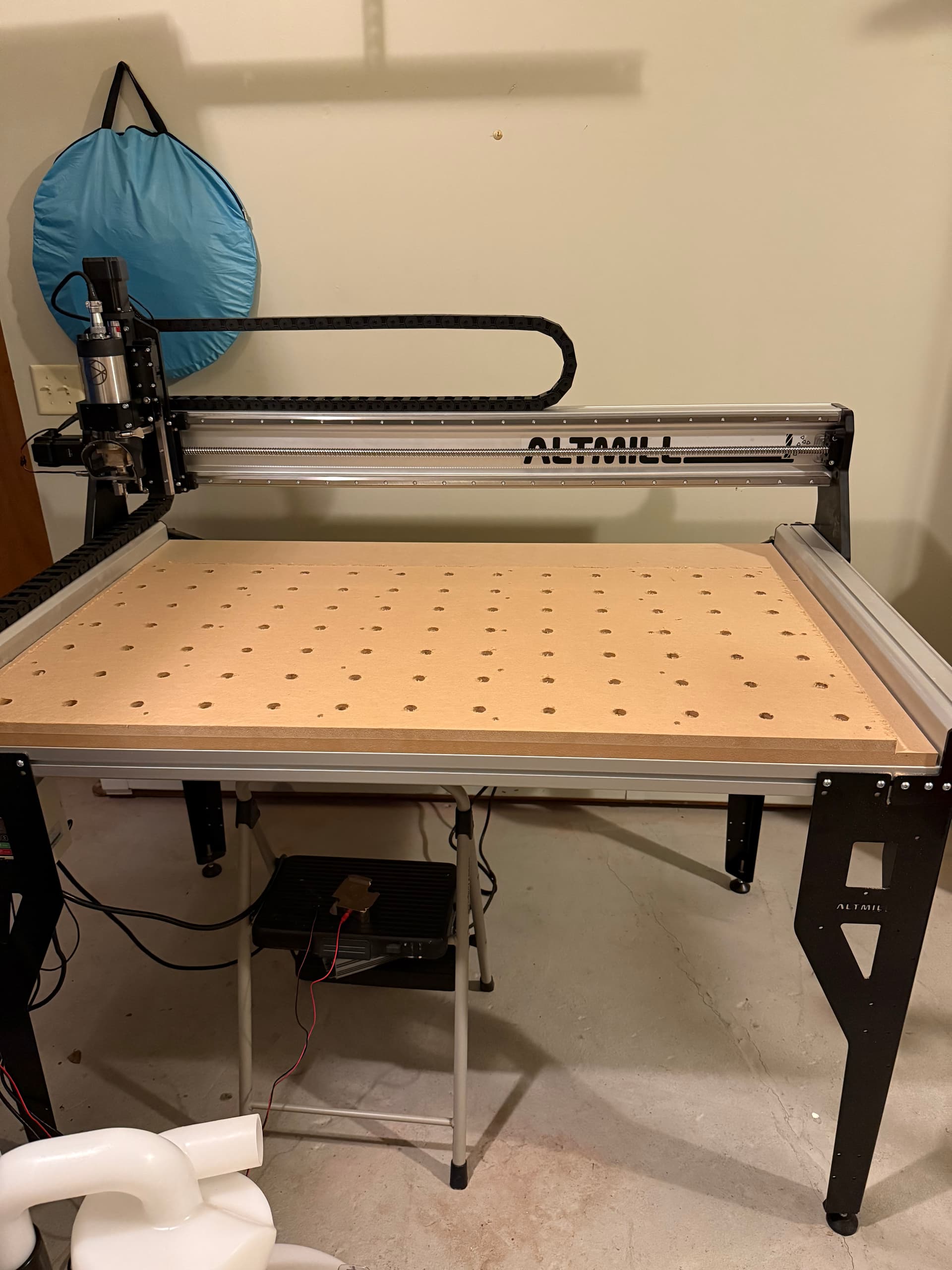
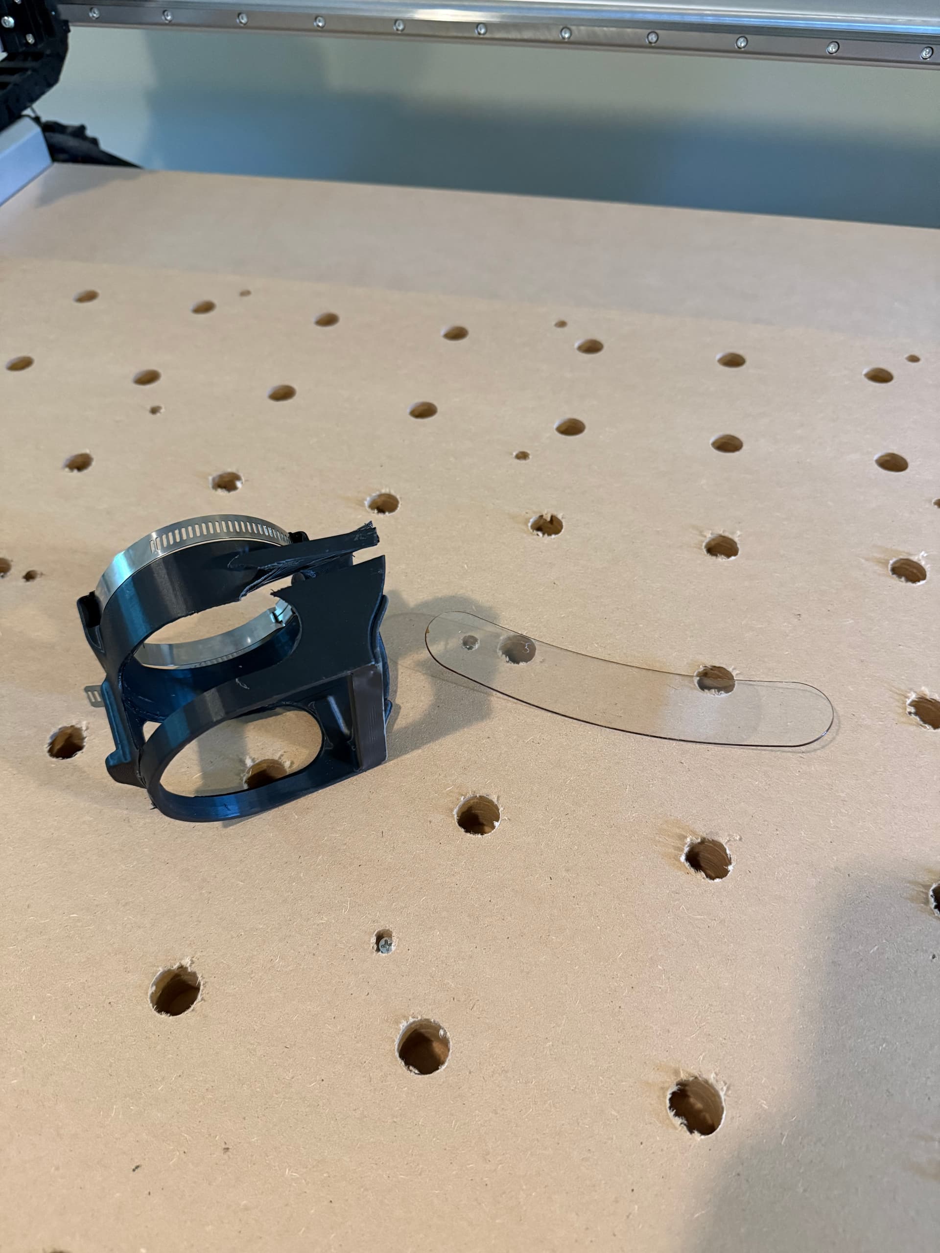
  • AltMill 2x4 with Sienci spindle and dust shoe
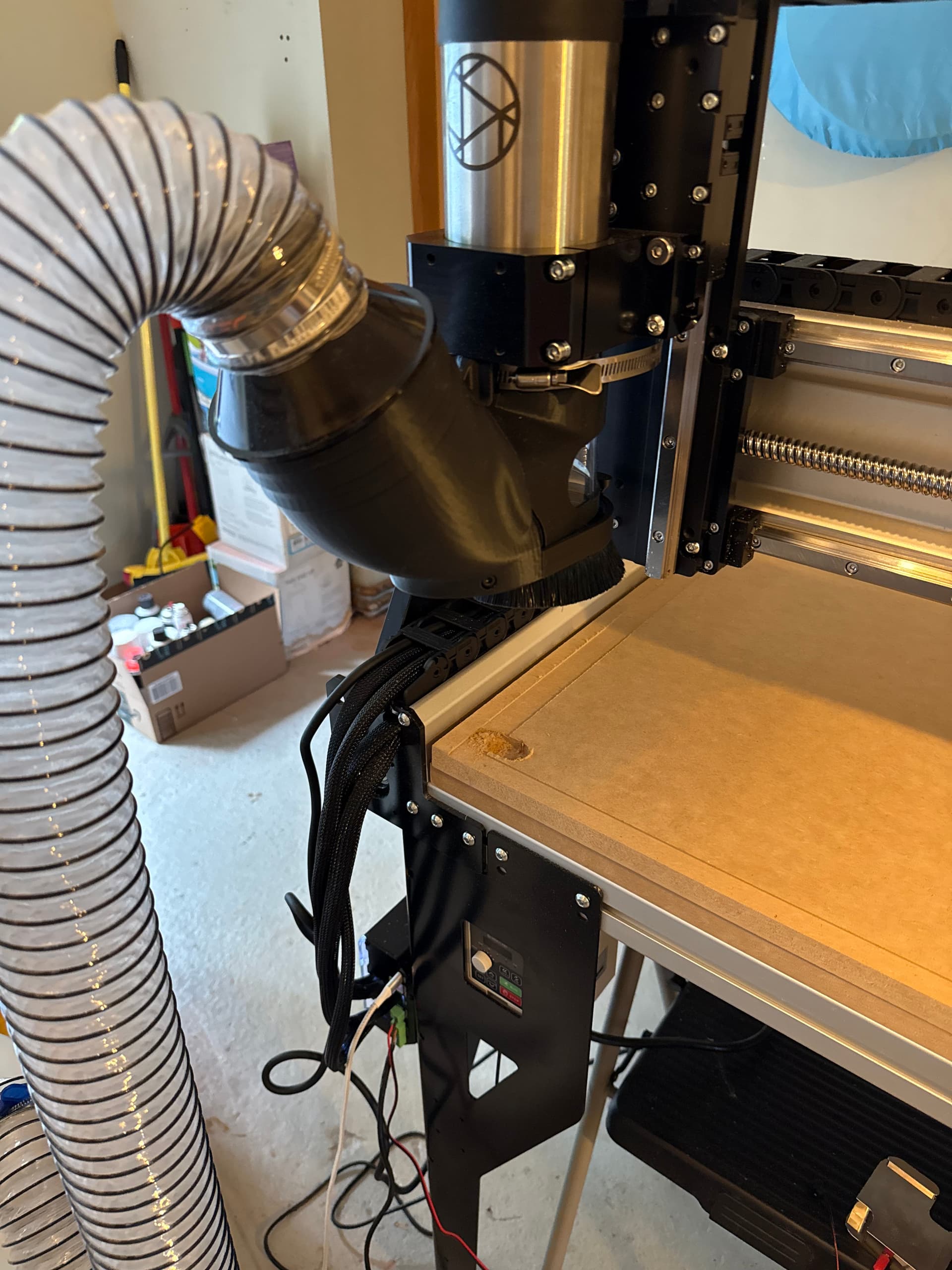
  • DeWalt Stealthsonic and a cyclone for dust collection. It uses a 2.5" hose so there’s a reducer for connecting into the dust shoe.

Surfacing my wasteboard

It was hard to figure out what size material I should use for the wasteboard. The docs are only specific to the 4x4, and suggest using a piece the exact size of the tabletop. It turns out that there’s no point to doing this on the 2x4, as the 4x4 has empty space under the gantry at Y0 (the area you can’t cut) but the 2x4 does not. Lesson learned: next time cut the piece to the available cutting area.

The first issue arose when setting up the cut to surface the wasteboard. The dust shoe crashes into the side rails when you’re at the limit of the cutting area. So I detached the shoe, and decided I’d start the job without it then add it back on once the perimeter had been cleared. First, that flung MDF dust literally everywhere. I do not at all recommend using this machine without dust collection for any duration on any material (but especially not MDF).

Then, when I stopped the job and installed the dust boot I discovered that I didn’t properly understand GSender’s “restart at line” function. Not exactly sure what went wrong (I’ll be researching that in the coming days), but on restarting the job it zoomed very quickly to the front-left corner and buried the bit in the wasteboard, stalling the spindle. A bit spooky, but I was able to recover and finish the job, albeit with an ugly scar on the wasteboard.

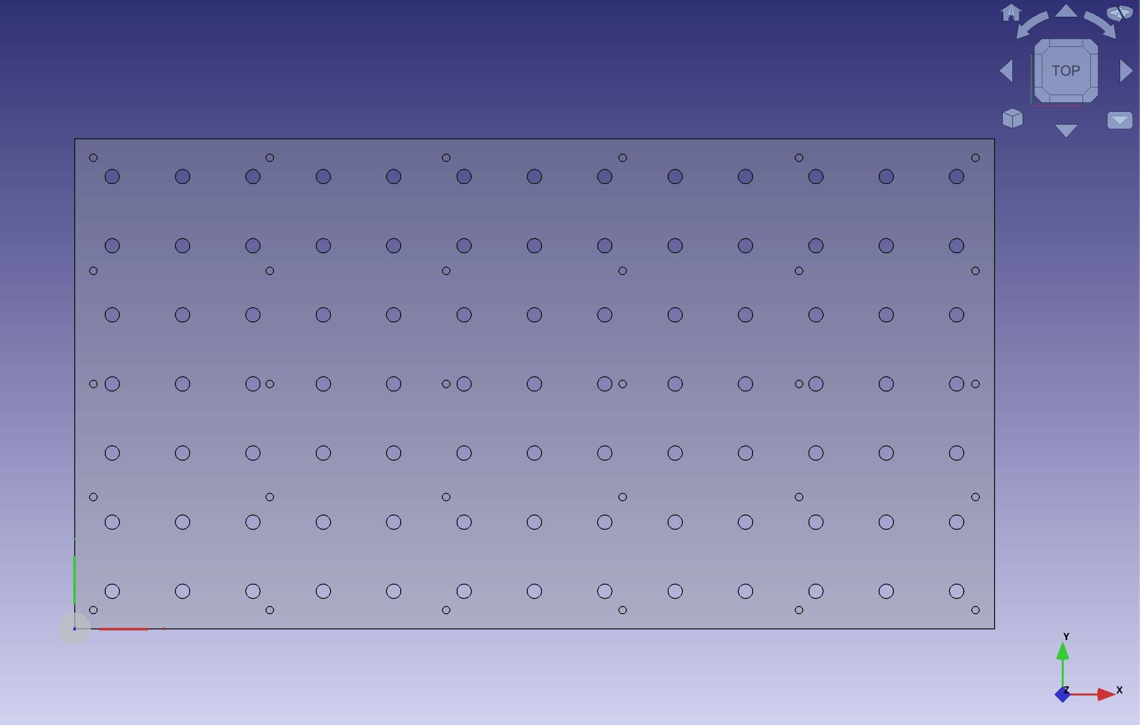
I have some more MDF, so I’ll be remaking the wasteboard. Even though I’m not using T-track I may just use the slat design so that I can build up a surface out of smaller scraps. Can anyone offer tips on positioning? I want to make sure I cover as much of the cutting area as possible without having parts outside the window which can’t be level with the others. I’m also thinking of spraying a single coat of shellac on the finished wasteboard just to give it a little protection from humidity and harden the surface a bit.

Overall impressions

I’m impressed at how well the AltMill came together for me. Got all the heavy assembly stuff done in a few hours one weekend with my dad, then finished the wiring and other setup incrementally over a few days where I had the time. The machine seems to be trammed perfectly (or as near as it matters) – the flattened surface has visible lines kind of like a freshly mowed lawn, but I can’t feel or measure them. It looks like a precision machined surface, which is pretty much what it is.

I’m less enthused with the dust shoe, it’s a bit cumbersome to work with and I may change it out for another before too long. On a similar note, I was playing with the AutoZero touch plate and found it very difficult to get an XYZ reading on. Z is easy, but when probing for X and Y it puts enough lateral pressure on the plate to make it jump off the corner it’s on, even with me holding it down. I didn’t get a single successful probe out of 10 or so. I probably just have to do some more learning on that tool, however.

Next steps

  • Better cable management, I’ve got a lot of wires dangling in a very trippy area
  • New wasteboard with dog holes
  • An actual project that isn’t just machine setup
3 Likes

@cnasc Welcome to the group!

I agree with that statement, MDF is super dusty. I built an enclosure for my LongMill and so glad I did as it keeps all that contained when surfacing the spoil board. Enclosing an AltMill might be harder with the incorporated table but I don’t know for sure. An enclosure was part of my original table design to help keep the room clean and contain fumes from laser cutting.

I’ll explain what I did but you might have to change things for an AltMill. Because I have a wooden table top under the spoil board I am able to mark the corners of the machines travel range with a V-bit. Then I made the spoil board to cover that area. That ensures that I can surface the whole area and with anything other than a V-bit your actual working area would be smaller by the radius of the bit. Maybe with an AltMill you can put a piece of plywood etc on temporarily and mark the corners and then measure from some reference point on the machine frame. Or maybe you don’t need the plywood if there is some place to measure with a carpenters square or such from the frame to the point of the V-bit.

I’m curious about others thoughts on this because I’ve wondered if it would work or if applying shellac or poly would make the surface swell and require resurfacing again.

Congratulations on what you have accomplished so far. Assembly is done! Let the good times roll!

Thanks for the warm welcome!

Yep, part of me wanted to make an enclosure for both dust containment and noise but the AltMill doesn’t really accommodate it. Luckily I can say with the AltMill and dust collector going it isn’t too loud. I wouldn’t want to stand around it all day without hearing protection, but it isn’t going to wake up the kids (I’m in the garage, which is attached to the house).

Building an enclosure around the AltMill seems like it would require building a tiny room around the machine. And the AltMill, even the 2x4, is big enough that it really doesn’t need any extra stuff around it.

That is an interesting idea, very analog but it makes sense for bootstrapping the machine.

Heh I’ll gladly be the guinea pig and report back!

1 Like

I was thinking more about your spoil board and remembered that a CNC machine is pretty good at measuring itself. If you home or move to the front left and zero XY then jog to the back right your dimensions are shown in gSender as long as the mill is calibrated. Then you only have to worry about the position of the spoil board.

On second thought, I’ve actually already got an indication of the cutting area from the surfacing pass I ran. I’ll probably just cut down the sheet to remove the back area for future use and trim the side a bit to remove the gouge. I shouldn’t miss an inch or so out of the 50 available on the X axis. Then it’s just a matter of laying out my screw holes and dog holes.

1 Like

After some more difficulty, we have a wasteboard!

I know I could have made this a lot easier on myself by just cutting some MDF with a saw and screwing it down, but I really wanted to do as much of this as possible on the machine and I did end up learning a lot in the process (including learning what I don’t know and need to read up more on).

The technical issues

When I first went in this evening to get started, one of the Y-axis motors wasn’t spinning. One side would move while the other stayed in place, jarring the whole machine and table and causing an alarm in GSender. Ultimately a power cycle brought it back :man_shrugging:. Definitely something to keep an eye on (loose connection somewhere?) but once it was back up and running it was good.

The wasteboard design

I measured the surfaced area on the sheet on the table, subtracted a bit to give myself a little margin, and laid out a wasteboard in FreeCad. The most critical things here were:

  • the size of the dogholes (I ended up undersized, had to change the design and run the program again)
  • the distance between them. I have doghole clamps that have 4 inches of travel, so I needed the offset between holes to be less than 4 inches. I played around with my design until I had good offsets and (importantly) no collisions with screwholes. There’s probably a better way to do this, but I’m still new at CAD.

The machining

I did this in 3 steps:

  1. Screw holes (just the countersinks really)
  2. Dog holes
  3. Exterior profile

To begin with the MDF was just clamped to the table in the area where the cutter doesn’t reach. I did the screwholes in one pass, then put a screw in each one so we’d have much more security during the bigger operations.

Then I did the dogholes. I started off with the nominal 19mm that the dogs are advertised as, then test fit. They could go in, but I needed pliers to pull them out. I stepped it up to 19.1mm, generated new G-code, and ran the operation again. That resulted in a perfect fit, snug but easily removed when needed.

Finally, the profile. Since I’d already surfaced the MDF down 1mm to begin with, I set the depth of the profile to 18mm. This left an onionskin at the bottom which I was able to slice with a box cutter and pull away the leftover MDF. The profile was done in 2 passes, and made an awful high-pitched racket (most of the cutting up until now had been completely inoffensive). Not sure if my speeds or cutting direction were wrong, if that was just the sound an endmill makes when slotting MDF, or something else.

edit: I’m looking back at the speeds and feeds chart for the bit, and I have no idea where I got the idea that a 9mm stepdown was right. I must have looked at the wrong column and I’m guessing that’s why the profile cut sounded so awful.

There are some fuzzies all over (used an upcut endmill), but I think the next surfacing pass will sort that out.

Next steps

  • I need to learn more about the machining side of CNC machining
    • speeds and feeds
    • in the event I have to work my way up to a fitment, is there a way for me to just expand or deepen whatever I just cut without running a brand new program from the start again?
  • I’ll surface the board again and spray a coat or two of shellac on it. From what I’ve read online I don’t think I’ll have to worry about swelling or warping. The dogholes go into the table surface a bit, which will be great for lining everything back up.
  • I am definitely changing the dust boot. I managed to cut myself on it while trying to remove it.
  • I think my first “real” project on this will be a simple V carve, stay tuned
1 Like

You might want to make some stiffeners for the legs. The table will shake when you have fast feed rates.

Ah, interesting, so some of that racket was actually the whole thing moving around?

I was going to suggest that 9mm passes seem very aggressive but I guess you figured that out. I’ve noticed that FreeCAD seems to default to the tool diameter for the pass depth and that’s too aggressive for my LongMill Mk1. I usually use 1/3 the bit diameter for the pass depth but I would expect the AltMill to be able to do more. I’d try 1/2 the diameter for end mills and then adjust from there. That is if the AltMill crowd doesn’t say to do more.

Not that I’m aware of, you need to generate new G-code so that means back to the CAD/CAM. There are some things that you can do depending on the CAD package. I’m just getting into FreeCAD so I need to learn to make things parametric. FreeCAD has some sort of spreadsheet that you can store variables in and then you can use math expressions to set the size of things. Then you can change the size of all your holes at once.

The other thing that works with pockets, for expansion but not deepening, is you can switch to a profile on the inside instead of a pocket after the first try so your not cutting air for most of the pocket. If your doing a through cut you can just start out with an inner profile and leave the center of your hole instead of making more sawdust.

I think it’s good to use the mill for your wasteboard. You know that your dog holes are square to the machine because the machine made them. If you did them with a drill press or something would they all be exactly inline and installed perfectly square? Not if I did it that’s for sure.

Looking forward to your V-carve. I’ve done that with FreeCAD, now I need to try a V-carve inlay.

Good luck!

@cnasc probably not. Unless the table is hitting a wall. But it’s still disconcerting to see it shake like that.

Snuck out at lunch to run a surfacing pass on the wasteboard and disaster struck again.

Dust boot crashed against the side of the machine and disintegrated. Even with my wasteboard off the edge of the cutting area by a bit, this boot is just too wide to surface with. Looks like I’m out of commission until the replacement dust boot gets here.

1 Like