For my first real project on the CNC machine, I wanted to make a real thing and I settled on a stool; as both my wife and I are pretty vertically challenged, stools are really an asset in almost every room.
I really liked the work of Daniel Groß on his “Simple Stool” and wanted to replicate it in imperial sized materials rather than metric. It seemed like a great chance to learn fusion and try to perfect an overall workflow. My overall workflow is: create sketches for all the parts; extrude into solids; use mirroring and union operations to complete the design; and then use Fusion 360 to generate .nc files for all the parts. Finally, I have a raspberry pi hooked up to the long mill running CNCjs and I can connect directly to it from the computer in my office where I do the design work to send it designs; then walk to the machine and run the program from a tablet or from my phone after setting the material and origin up.
So first off, in my opinion to use Fusion well requires a bit of practice. I followed some tutorial videos and then set off to implement the stool. I wanted to have separate sketches for each of the three distinct shapes: the stool top, the braces (which I call struts [sic]), and the legs. It can be hard to create fully constrained sketches in fusion without something to anchor to, so I started by making a sketch of the footprint of each of these pieces using construction rectangles, like so:
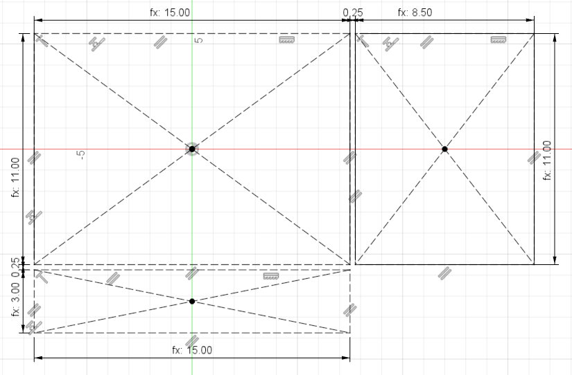
You’ll notice perhaps that all the dimensions are labeled “fx” meaning that they are computed rather than constants; they come from the parameter list for the design. To access parameters in fusion, I use the “s” short cut then type “param”:
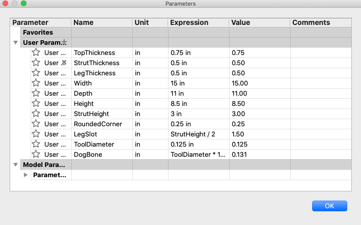
As you can see here I am designing for a 3/4" thick top, 1/2" thick legs, because those are the dimensions of MDF I had lying around from my enclosure project and I didn’t want to use expensive material for a stool that I knew I’d have to cut multiple times before I was satisfied with it. In order to make the stool easy to scale I meant to use parameters for every important dimension – but I wasn’t thorough enough and some of the arcs are not like that, so that the stool scales OK but not perfectly. I still plan to go back and fix up those dimensions which aren’t based on the stool parameters so that the stool can easily scale arbitrarily.
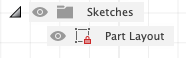
The sketch for layout completed, I saved it and called it “Part Layout”. It appears in my tree with a lock on it, which as far as I’m concerned is a necessary prerequisite to considering a sketch done in fusion if you don’t want to mess it up in a major way with a minor parameter change later:
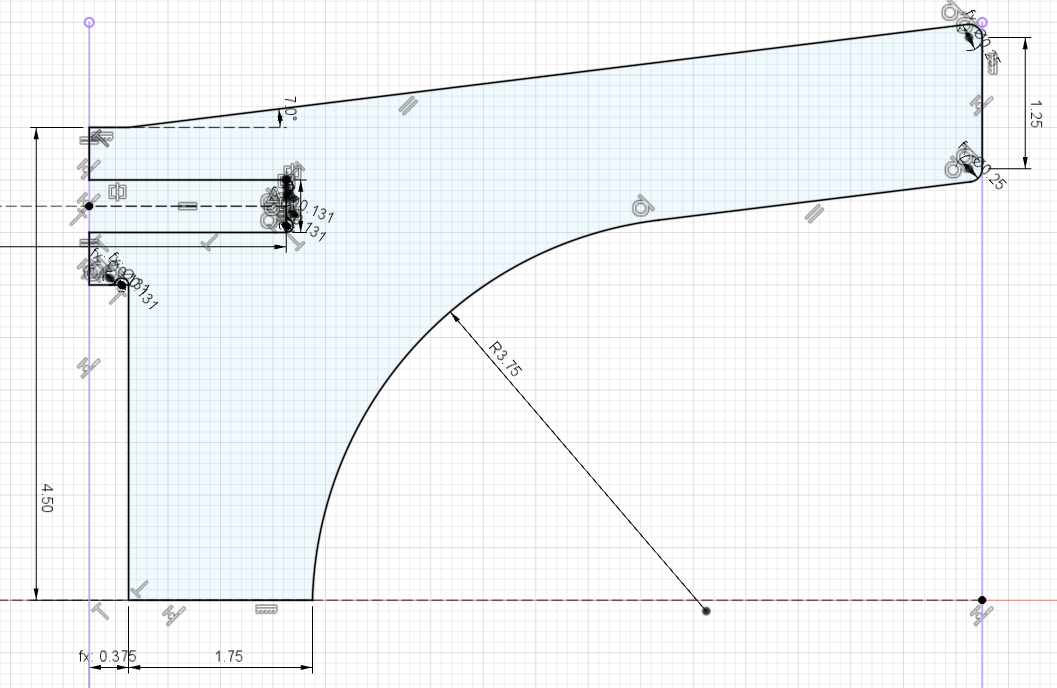
Then I started working on the strut. Here is the “completed” sketch:
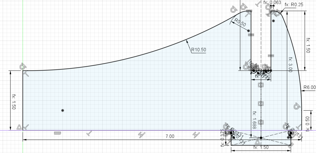
Note some problems with it: The R6 and R10.5 needed to be based on some other dimension or made directly into variables.
Note some tricks in it: in order to create tangency with the arc on the other side after mirroring the solid later, there is an infinitesimal straight line coming off the top left corner (you can tell because of the perpendicular constraint in that corner) enabling the arc to be tangent to the tiny line segment and therefore to the arc on the other side of the mirror so that there isn’t a pointy top to the arch. The slot is correctly thicknessed to fit the leg, and the dogbones are designed so that they’ll disappear into the connection when assembled and you won’t see any ugly holes in the stool when it is assembled. There is no allowance for slack, making this part fit very tightly with the leg part (which I like but may be bad design): the friction fit is so tight you cannot easily get the parts apart after assembly.
I had a lot of trouble preserving my constraints if I trimmed out the dogbones in the sketch. So instead I left them untrimmed and just didn’t extrude them:
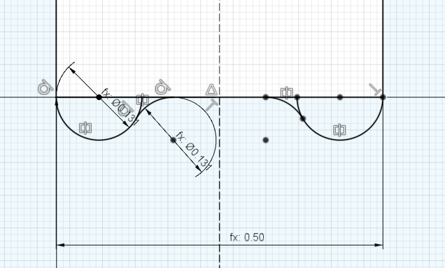
Some finer points about how this is designed: The radius is taken from the tool diameter * 1.05 and computed and stored as a variable called “DogBone” in the parameters shown above; the extra curve on the way out of the dog bone makes for a smoother cutting toolpath than just driving in and out leaving a sharp corner; and the drawing only exists on one side of the line of symmetry and is mirrored to the other side using the sketch mirror tool. In this say any changes needed here only occur once and will affect both sides.
Finally note the line of symmetry projects way beyond the sketch; using the part layout, I ensured this line went through the stool top so that I’d later be able to exactly locate the geometry to cut the socket that receives the top of the strut.
Next up I drew the sketch for the leg:
There is no really interesting new thing here; the same mistakes and features as exist on the strut are repeated. For both the strut and the leg when sketching I found it convenient to use a dimension from the footprint of the sketch to a corner of the actual part to constrain a starting point on the outline, and then work my way around the outline with perpendicular and tangent and dimension constraints until the entire sketch was fully constrained. There is some problem with this sketch which shades in the slot for no reason I could discover and rather than draw the whole thing again when it works in practice I just lived with it.
The leg is machined with stock to leave of -0.1mm to create a bit of slack for inserting it into the top and into the strut.
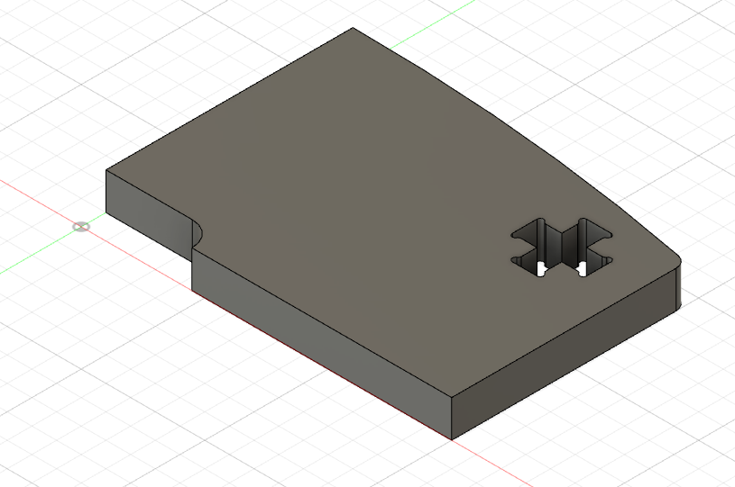
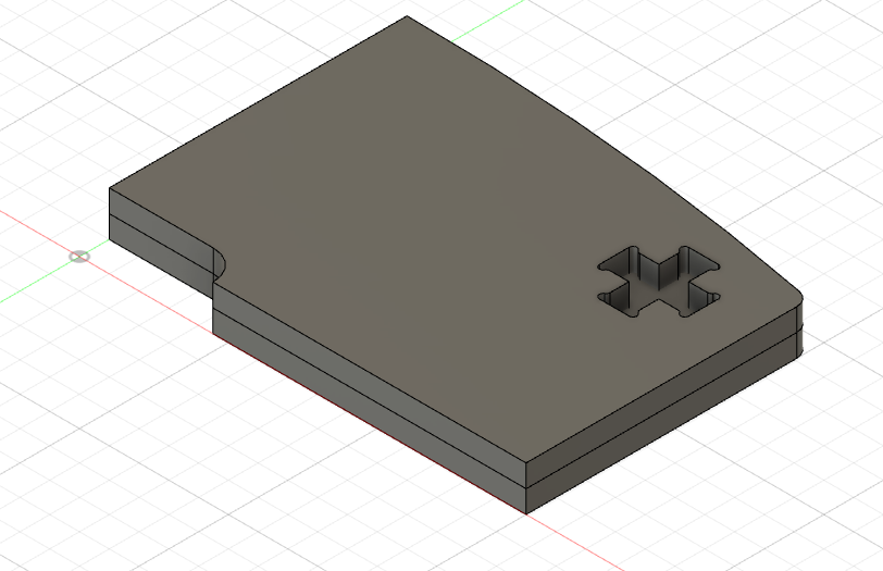
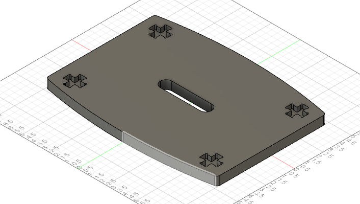
Finally the top:
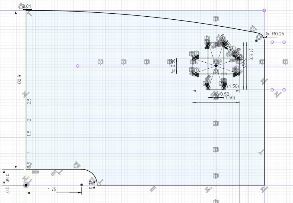
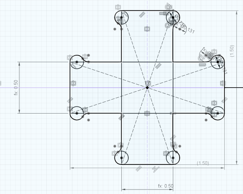
Here the point of doing the other sketches first becomes apparent; their connection to the + shaped hole is visible and enables me to make the hole in exactly the right spot. The hole is machined with stock to leave of between -0.1 and -0.2mm to create enough slack to be able to easily insert the legs (-0.2 slides in easily and supports everything by friction, but pulls apart easily; -0.1 needs to be stomped on to get the parts to sit together and then cannot be easily taken apart without tools). The detail view of the hole itself shows the original dogbones and their 6 mirrored cousins:
Sketches complete, it’s time to extrude:
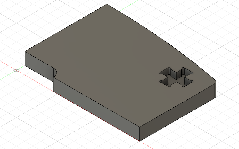
The first extrude is for the full top thickness to create a stool top with holes for the feet. The second extrude is solid to fill in the the socket for the feet:
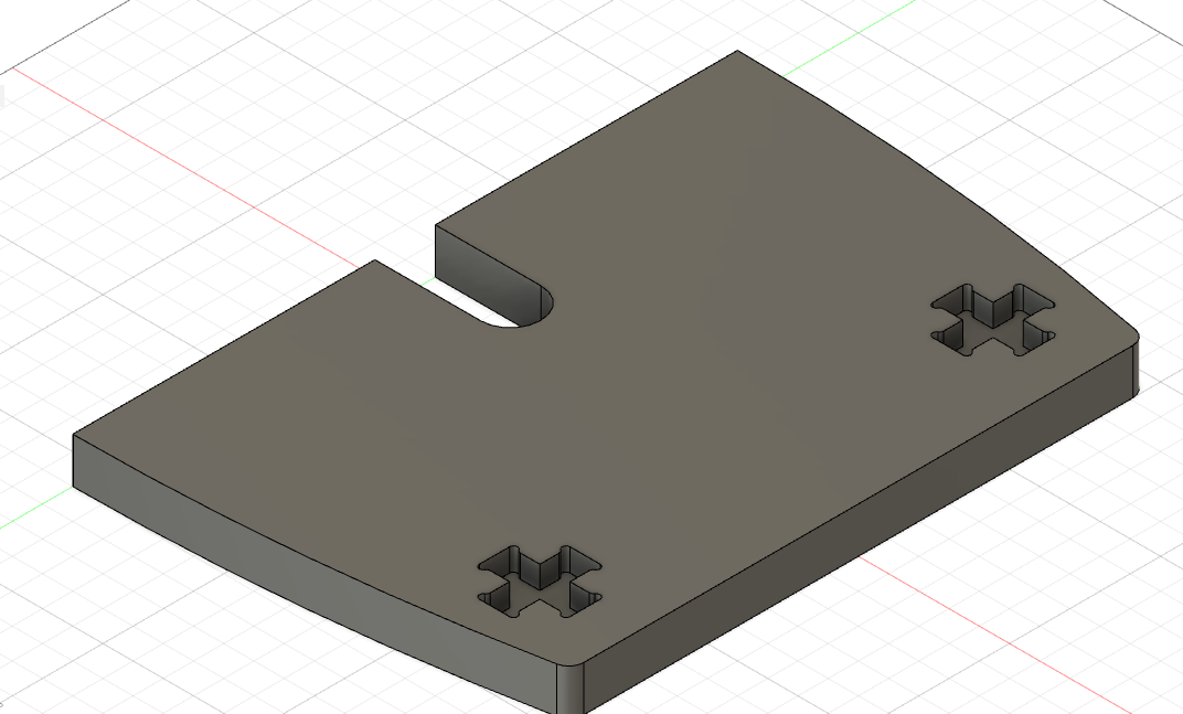
The third operation unions those two bodies - I don’t want the line indicating that there are two shapes here:
Then two mirror operations round out the job:
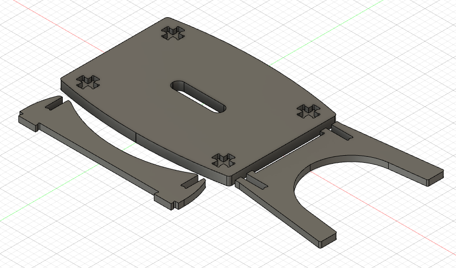
Finally, extrude and mirror the other parts:
Then I swiched over to manufacture I used a 2D pocket for the pockets, then contour cuts for the handle and outline of the stool top. This I wanted as one program, so I wound up using a 1/8" bit for the whole thing even though the pockets would be more efficiently machined with an 1/4" bit because fusion doesn’t support tool changes in a single program unless you pay for it. I could have also made two separate programs for the top but this seemed more error prone to me.
The strut and leg are cut with a contour cut.
In all cases I allowed only 5mm of step down per cut and set the origin to the lower left corner of the stock. In practice the origin can be anywhere above the sheet of MDF which I secured to my wasteboard with deck screws for a rock solid workholding, and cut out without tabs.
Once the top was cut, I put a roundover bit in the long mill, manually adjusted the height, and used it like an upside-down router table to route a softer edge onto both sides of the top edge and the handle edge. The completed result before painting:
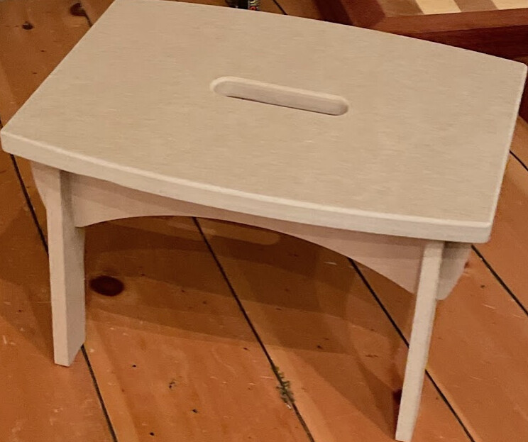
Due to the pandemic I’ve had trouble sourcing paint so I’ll have to make a separate post about finishing the project.
Feedback more than welcome.
Thanks!