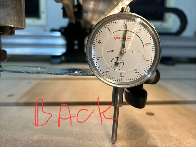
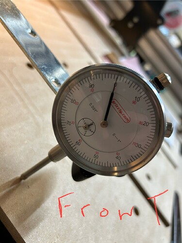
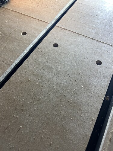
I finally got around to flattening my spoil board . It well and I was pleased with the results . I do have some noticeable lines in the top.
Question 1. Why would the lines be more pronounced at the back of the table then at the front ?
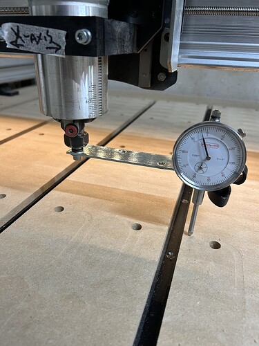
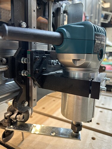
When I set up my tram meter the x axis is only slightly off . The Y axis is definitely off by more . If you were getting these reading would you attempt to adjust the router mount . If so how ?
!
To adjust the angle of the router for front or back tilt I would loosen the bolts that fasten the X gantry to the gantry plates. Then you can use the play in the bolt holes to adjust the tilt.
You can use a bar clamp clamped to the X beam to get some leverage. Use one with plastic or rubber pads or use a towel so you don’t scratch up your machine. Your readings would suggest that the router is tilted towards the back at the top. A helper is useful if have one to tighten the bolts while you hold the beam at the proper angle. You can do it solo if you put some blocks and a wedge to hold the clamp while you tighten the bolts. I used a carpenters square against the plate that has the Z rails and the spoil board to get the Z axis perpendicular to the Y axis.
Then you resurface, you shouldn’t have to take of much, and see if the lines are reduced or gone.
Good luck!
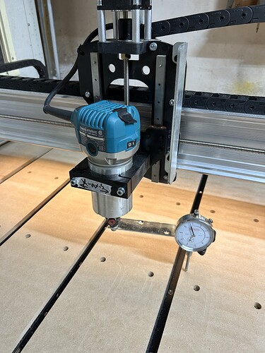
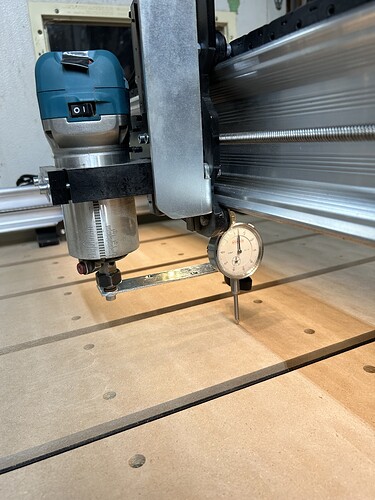
@fonthillhd It’s not clear from your pics how you are taking the measurement. Can you explain how the dial gauge is attached to the router mount, please? I’m asking because if you are measuring two different points by jogging the machine from front to back, that is not how to determine if you need to tram.
That’s a good point Grant, my advise assumed that it was spun to get from front to back and you know what can happen when you assume!
EDIT: Taking a close look I think he spun it because in the back pic you can just see the collet nut, I think, and it’s beneath the X rail. In the front picture there is not much background but it doesn’t seem to match and the X rail is to the left.
@_Michael You could very well be correct, Michael. I just thought that it was worth asking since the pics are not clear about @fonthillhd methods.
I just got home and looked at the mount for my router and call me stupid but I cannot figure out which bolts you are referring to
@fonthillhd Tks, Frank. I’ll stay out of this conversation since I am in a one-person minority on this question. ![]()
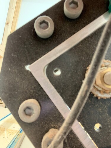
The bolts at either end of the X axis that connect the X rail to the Y rails by way of a metal plate with v-wheels. I think they are called gantry plates. The idea is to get the plate behind the router, the one with the Z linear bearing perpendicular to the spoil board by rotating the whole X rail/beam. Other than the anti-backlash bolts and the v-wheels the only adjustments that a LongMill has is in the ‘bolt slop’ as I call it.
I wouldn’t as the bolts I’m talking about are pretty far away from what your adjusting, hence the blocks and wedges or a helper.
My machine is a MK1 so it’s different and the camera is really close because my enclosure is tight on the sides. I have 4 bolts on each side to loosen to do the adjustment. The nut on the right and centered vertically is the end of the X lead screw. You have a MK2 so it looks different but the principle is the same.
Ok I see now what you’re talking about . I will try this on Sunday when I get out to shop again
