Check me out … I am the noob rolling with Fusion 360 and trying to cut some fret slots for a guitar. I have had a good model of the fretboard for weeks but struggled a lot with CAD and CAM interaction. Much of my consternation was related to the geometry of the fret slots in the model and Fusions apparent refusal to cut a .023" slot with a .023" tool.
Last night I finally executed the proper process to project a line onto a curved surface without it being an extrusion. I used the trace action in the CAM to program the cutting of the slots. Each line being projected is measured from the nut (end of the fret board), so I would not suspect some sort of cumulative error as I go up the neck but only the 4th fret slot appears to be dead on. The first 3 are a little short and 5-20 are all a little long.
Anybody else have trouble with cutting that requires precision down to thousandths of an inch? Anything I need to calibrate on the Longmill? The X axis is most suspect in this process.
On a positive note, my inlay testing went flawlessly.
Fusion, and probably other CAM programs, will not cut a slot using the ‘Slot’ toolpath unless the cutter diameter is less than the slot width. Instead of using the slot toolpath, cut a full depth pocket using a linear approach and a lower cut speed since you will be cutting on both sides and front of the cutter for the complete DOC.
Thanks Bill. I abandoned any slot or pocket option for the Trace toolpath against a line projected on the fretboard. The cuts just are not at the measurements specified. I suppose a swing at a toolpath making the default .0004 variance something crazy like .00001.
I have this issue with Aspire. I just lie to Aspire and say it is a .022 bit and cut ON the (fret) line. Frets go where they are supposed to, guitars intonate correctly and Aspire is non the wiser for my lie. For amplifier component mounting holes, I just add .001" to the diameter (.125) and Aspire does not reject the .125" bit. Weird but it must have to pass some yea/nea logic test to work.
I have validated all of the measurements in the drawing. I set all of the tolerances to .0001, rotated the model 90 degrees, exported those new toolpaths, and cut again so see if the issue followed one axis or another. It didn’t matter. The boards are identical: both wrong exactly the same way.
Am I missing a calibration step somewhere? Am I expecting too much of this machine?
nothing so far. i opened a case since this thread went dead fairly quickly. thankfully @whittamps hit me yesterday and is going to send me some gcode that he uses and i’ll see what gets cut from there. chris made some suggestions at how to test some more in my trouble ticket but i’m not confident that what he suggested will change my results.
Not really. It would be interesting to put a dial indicator on the spindle and see how accurate the travel is compared to the DRO screen in UGS. In an open loop CNC you don’t have feedback that tells the GCode sender how far you’ve actually gone - it’s relying on the motor’s step degrees being translated by the threads per inch of the lead screw.
That should be accurate but you’d be hard pressed to get 0.0001" tolerance on a $250,000 CNC mill unless your toolholding, workholding and workpiece were extremely stable - in mould-making we used to have to control shop temperature for that level of precision.
But I can hardly think that frets need that level of precision anyway. A master woodsmith is hard pressed to hold 1/64th (0.0156") or “15 thou” in common usage although it’s closer to 16 thou. There are a lot of really nice handmade guitars I’ve played and while my ear isn’t perfect, intonation seemed fine.
If your first few are short, then one is right on, and then they go long and longer, I can’t help suspect a math issue somewhere. The image in my mind is an indicator on a forex chart where the lines get increasingly further apart based on a coefficient and making a decimal location error on that constant.
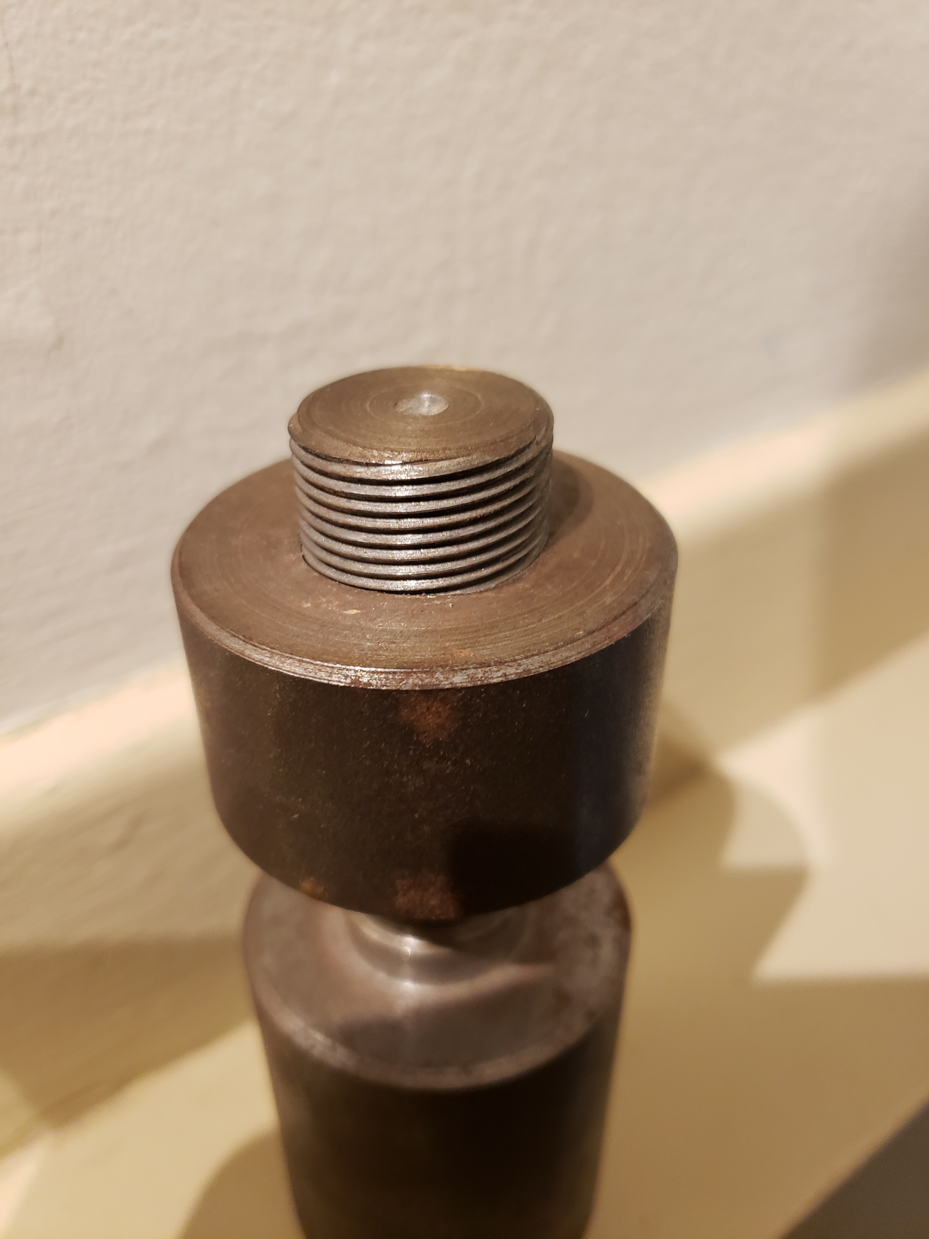
Keep it up - there’s always a way! Here’s my personal reminder I keep handy:
It’s a 4-start threaded stud and matching nut I turned in trade school 25 years ago on an old worn-out lathe with no DRO and about 30 thou of backlash, with cobalt cutters I ground myself, for no reason other than my instructor said it couldn’t be done.