I am new to Fusion 360 and I have a designed a spoil board and generated a tool path for the spoil board. The tool path executes fine except boring into the spoil board. I am zeroing the Z axis off of the spoil board. I have a ticket open with Fusion 360 and they have look the fdz file and tool path and said everything looks good. I using a 48 x 30 Longmill running Gsender. It simulates all of the boring but does not reach the top of the spoil board to even break the surface. Any one have any ideas?
Just for clarity - where are you setting the mill zero, and where is the toolpath zero? Can you post a screenshot? I have never had what you describe happen.
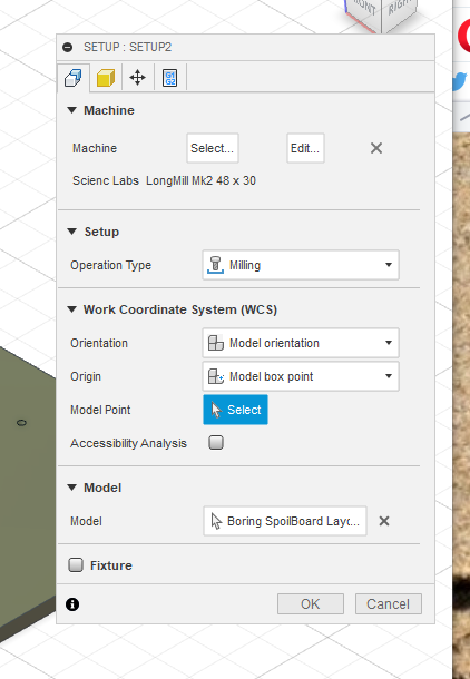
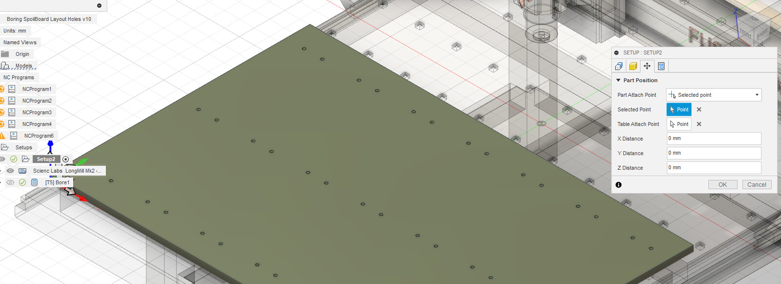
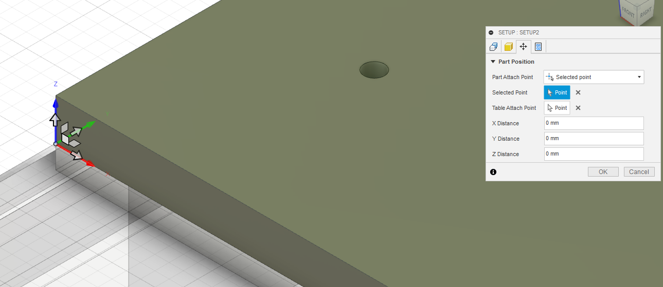
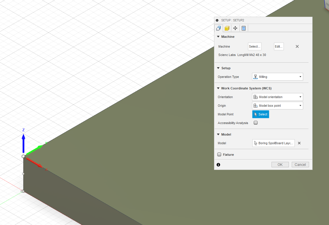
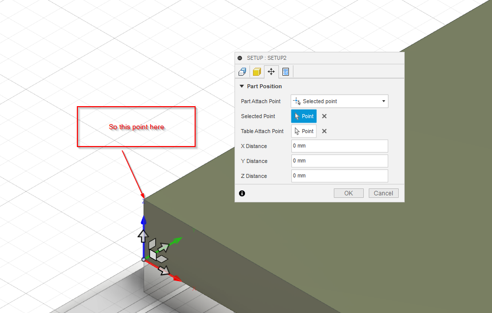
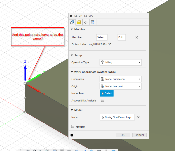
The one thing that comes to mind is the origin (the zero point) of the setup. It looks like the origin (shown in the third picture by the x,y,z arrows just under the project organizer) is set to the bottom of your workpiece. Where are you setting the machine z zero point? If you are setting it to the top of your workpiece, that explains the offset.
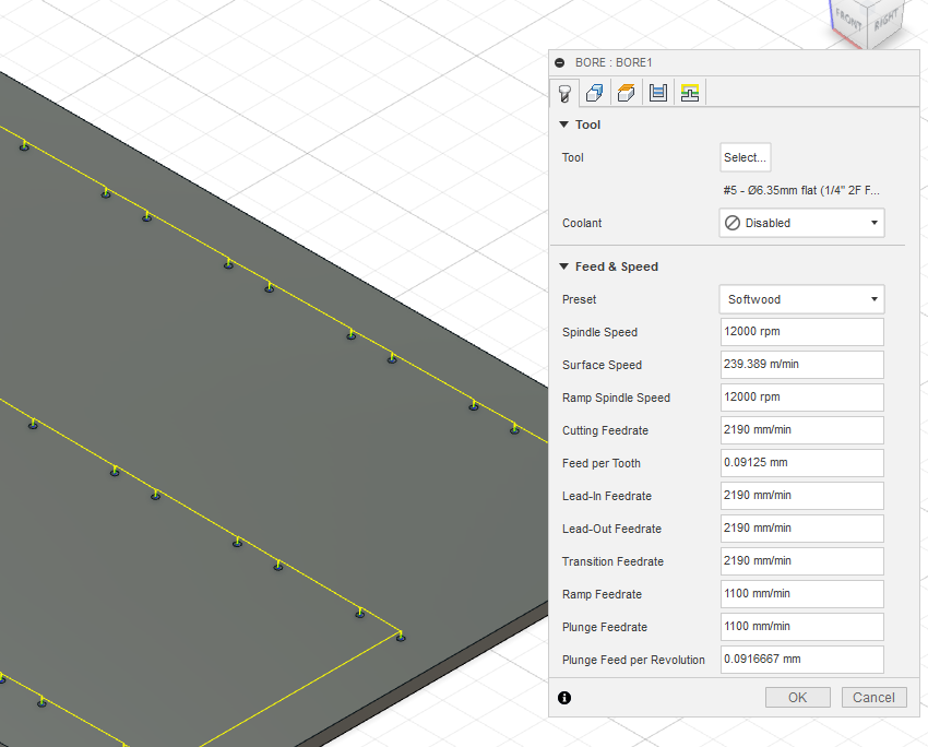
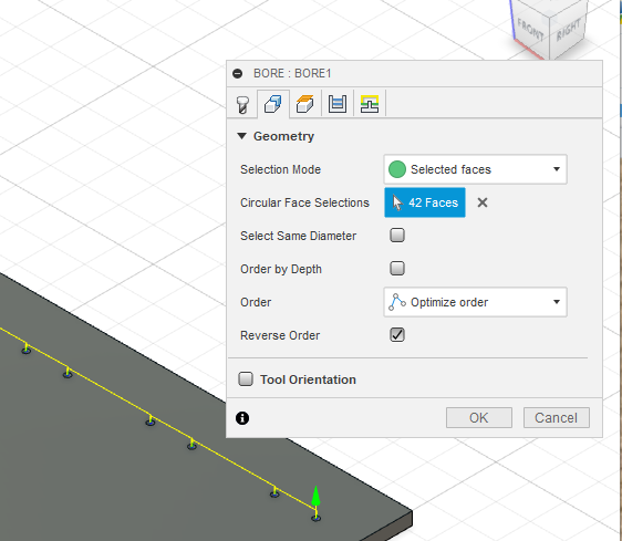
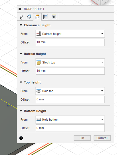
Why do you have an offset of 9mm for your bore bottom?
Can you share the f3d file?
Yes, the origin is set at the attachment point of the table or the bottom of the workpiece (added another screenshot). When you say machine Z zero point are you referring to setting the zero on router tool to the top of the workpiece if that is what you are asking then the answer is yes I am zeroing the mill to the top of the table just before I run the job.
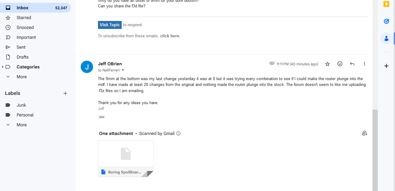
Emailed you the f3d file. The 9 mm was the last failed iteration my configure tool path of the many attempts prior to changing the bottom bore to 9mm of the 18.5mm mdf and so far nothing has worked.
I mentioned the table I was zeroing just before I run the job however I wanted to say workpiece.
Yep that will be the issue - with the origin where it is shown, you have to set the machine’s z zero to the same height (that is, the table). Setting the z zero to the top of the stock will cause all your toolpaths to run high by the thickness of your stock.
I didn’t get a file… How would you have my email address?
To clarify… Where is your wcs origin set in Fusion?
Hmmm… Maybe you can’t send attachments like that?
Can you upload it on the forum?
So, you’re WCS origin in Fusion is at the top of your model and you’re setting your Z-zero at the top of your stock through gSender? As @elbarsal said, those points have to be the same in software and in real life.
Sorry for the repetition, but I see conflicting information in your screenshots.
This is what I got when trying to upload the file: “Sorry, the file you are trying to upload is not authorized (authorized extensions: jpg, jpeg, png, gif, svg, nc, gcode, dxf, bmp, crv, crv3d, lbrn, pdf, rar, stl, txt, zip, c2d, json, art, lbrn2, skp, skm, hex, mp4).”
So what you and @elbarsal are saying these 2 points must be the same?
No. That’s impossible.
If you set your WCS origin here:
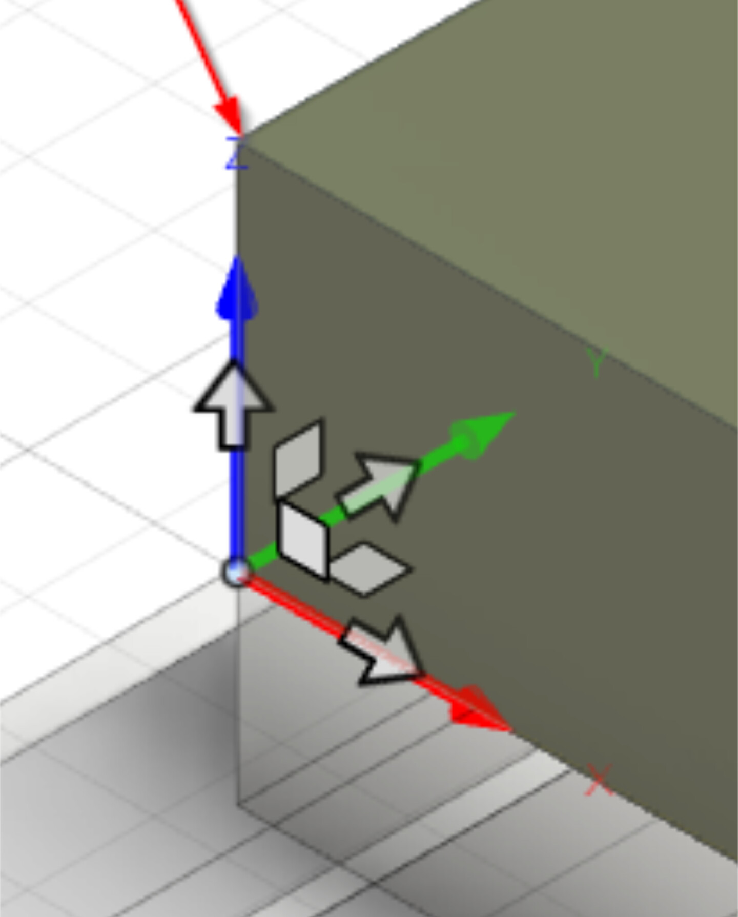
Your gcode will be such that all motion will be above Z0. Basically, you’re cutting down to Z0.
If your file was set up like this, and on your actual stock on your machine, you used gSender to set Z0 at the top of the stock, all of your gcode creates motion above the actual stock. Any through cuts would cut down TO Z0, which would all be in air.
The zero point in Fusion and the zero point on your actual piece of stock in your garage must be the same.
Use the top of stock for zero in fusion. And set Z-zero at the top of your stock on your real life machine.
Ok, going to try top of stock for zero in Fusion and zero at the top of stock on the cnc.
FYI, if you get that message you can zip the file and upload that because the .zip extension is allowed.
Happy carving!
One small note when picking an origin - it can be very useful to use the bottom of the stock as a reference, as that way it saves your spoil board.
Since stock isn’t typically truly the thickness it is labelled as (usually slightly undersized), if you set the zero at the top of the stock and cut full depth, you will cut into the spoil board. If you set the zero to the bottom of the stock (i.e. the surface of the spoil board) you will only graze the spoil board surface.
In either case, the origin in Fusion and the Z zero point for the machine need to be set to the same point, as you have learned - thankfully the way you did it cuts air - doing it the other way around would crash hard into your spoil board!
I’ve transitioned to doing most of my work that way. I’ll set my stock thickness in CAD to be just under the actual thickness, zero at the spoil board, and my first tool path surfaces the top of the stock to get down to the thickness set in CAD. Then all other tool paths have a nice flat surface at the right height to carve on.
EDIT: The other advantage of using the spoil board surface is that it’s always there! I’ve done some reliefs where all the original stock surface was removed before the last bit change.
I adjust my z-zero for the type of operation. Any through cuts use the wasteboard as a reference, but all others use the stock top.