gSender has a smaller bug fix release which combines the changes from 1.0.7 with some other fixes and new features.
We’ve also laid the groundwork for an edge version of gSender, in which people can opt into new features sooner with the caveat that they aren’t fully tested yet. More news on that soon.
As always, thank you everyone for contributing feedback and bug reports!
Fix for start g-code event not sending entire code block in some situations and make it more consistent in all situations
Firmware now highlights settings that are different from default for Sienci machines
Support for edge/beta channels for those who want to opt into new features for testing
Improvements to controller movement using joystick
Brighter cut lines in visualizer
More sensible timeout on fetching updates
MK2 12X30 configuration now properly selectable
Added Mist, flood, and stop coolant keyboard shortcuts
Fixed issue with surfacing spiral pattern where center strip could be missed with some parameters
Fixed issue in calibration where the direction it asked you to move gantries wasn’t correct in some situations.
Laser offset no longer resets to previous value on toggle of laser mode
Numerous surfacing tooltip and unit conversion issues fixed
Surfacing now lets you select M3 or M4 movement
Rapid position buttons now use $27 pulloff value for determining final positions
Outline tool now stores and restores modals on completion
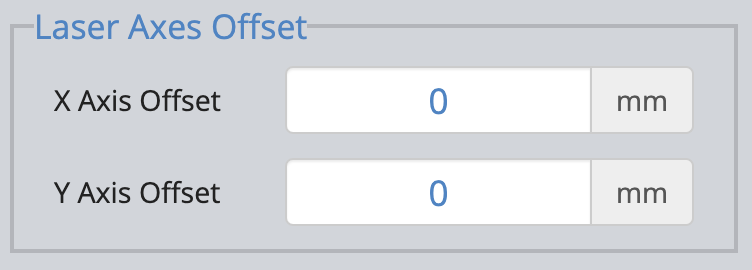
So I’m not sure I fully understand the Laser Axes Offset function in the Settings tab. I get that in some instances adding a laser changes the XY 0 from the spindle setting. As an example I enter +5 as the X offset and +10 as the Y offset. If I return the gantry to X0 Y 0 (i.e., click on the Go XY0 button) on the Spindle setting and then toggle to the Laser setting the DRO predictably changes to X 5 Y10. But if I then immediately switch back to the Spindle setting the DRO reads X-5 Y-10. Seems to me having not moved the gantry when I click on the Spindle toggle the DRO should subtract the offset values and read X0 Y0. I was hoping the new update when change this behavior. I’m sure I’m just not understanding how this is supposed to work. Either way I don’t use the toggle offset function when I work with the Laser on my CNC and it would be really nice if there was an option to disable applying the Axes Offset values when switching from Spindle to Laser.
This why I’m still on 1.0.4 (I think). Every time I get ready to upgrade, something else shows up to hold me back!
My offsets for laser are still being generated from my post processor which I have to specify when I save gCode. If the gSender offset function would work well, then I could use the same post for both router/spindle and laser toolpaths, and make the laser/spindle change in gSender.
@martindg To “disable” the offset function, simply enter 0 in each of the offset axes. You can still use the laser slider for the other functions - power and laser mode.
Except that I don’t believe that simply setting the offsets to 0 works to ‘disable’ the function. As an example:
First set the Laser Axes Offset to X0Y0
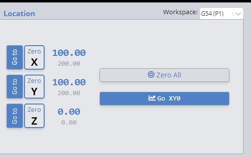
In the spindle mode I jog my machine to machine coordinates X100 Y100 (G53 X100Y100) and set this as X0Y0 for work coordinate system 1 (G54)
I toggle to the laser mode and the DRO still shows X0Y0 for WCS and X100Y100 for the MCS which is correct as I indicated there is no offset for the laser mode.
Next while in the Laser mode jog away from X0Y0 (e.g., G0 X100 Y100). The DRO now shows X100Y100 (WCS) and X200 Y200 (MCS). This is also correct.
Next toggle back to the Spindle mode. The WCS applies the XY 0 offsets from the settings and the DRO reads X0Y0 in the work coordinate system but the machine coordinate system now reads X200 Y200.
So when I started this example my spindle X0Y0 was set at MCS X100Y100. Toggling to the Laser mode and then back to the Spindle mode caused my Spindle XY0 to move from MCS X100Y100 to X200Y200. Seems to me that when I toggle from laser back to spindle my XY0 in the MCS should still be set to X`100Y100.
So setting the XY Axes Offsets in settings to 0 doesn’t seem to disable that offset function, it simply applies an offset of X0Y0. It works as long as you jog to X0Y0 before toggling between Laser and Spindle. This has bit me a couple times when I have jogged away from X0Y0 to remove the laser and insert a new bit in the spindle and then toggled from Laser back to Spindle without jogging back to X0Y0. IN these instances I have then lost my X0Y0 for my Spindle mode.
Again, I fully recognize that I simply may not be understanding how this is supposed to work but as I apply my offsets via my posts or via macros I would really prefer that this offset function built into gSender simply be completely disabled .
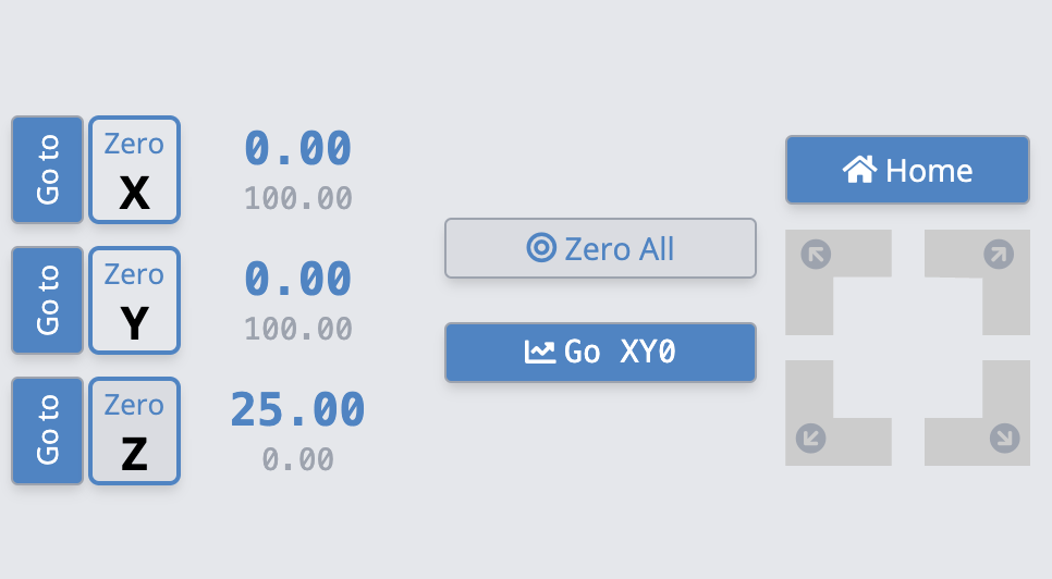
@martindg FWIW, I cannot re-create your problem. I followed your 5 steps exactly. At the end of those steps, WCS was X100Y100 and MCS was X200Y200. Attached is a screen shot of the GUI output after step 5. Toggling to spindle mode did not change the settings from step 4.
Step 3. Toggle to Laser Mode and DRO doesn’t change from previous image as the Axes Offsets were set to XY 0
Step 4. While in Laser mode jog to X100Y100. DRO now shows WCS X100 Y100 and MCS X200 Y200 (as it should).
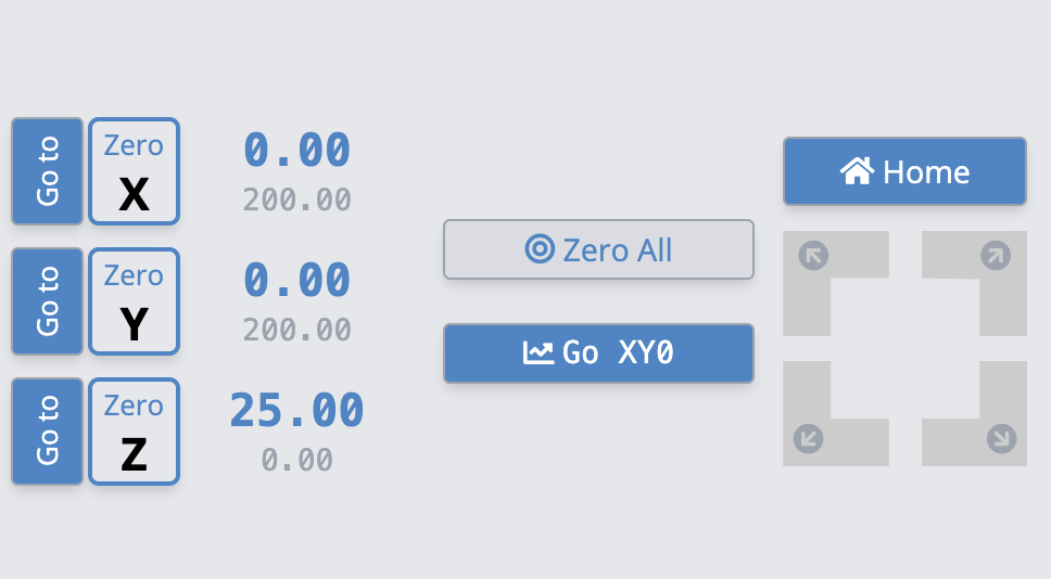
Step 5. Without jogging toggle to the Spindle Mode. The WCS XY now reverts to 0 but as my Axes Offset in Settings is XY0 it seems to me that the WCS should still be at XY 100 after toggling back to Spindle mode. Instead what has happened is the Spindle WCS XY 0 has been reset to MCS XY 200. After toggling from Laser to Spindle mode it seems to me that my machine should be in the same state as it was before I initially toggled into Laser mode and its not (i.e, Spindle WCS XY 0 at MCS XY 100) My WCS XY 0 has been shifted by 100 mm (from MCS XY 100 to MCS XY 200).
I guess I’m likely not making my issue clear but I remain convinced that the Laser Axes Offset setting is not being applied correctly (or at least what my brain tells me should be the correct implementation).
@martindg I think you are clear, Doug. This is just weird. (technical term ) When I get to where the DRO shows 100/200, toggling laser/spindle mode does nothing. I still end up, as shown in my screen cap, with 100/200. Like you, I am running 1.1.0
With luck, someone else can follow your steps and report their results. In the meantime, I suggest that you uninstall all versions of gSender and re-install 1.1.0. You will not lose any macros or settings.
@martindg I’m on windows. I wouldn’t think that it would make a difference, either. I’m sure that someone on the gSender team at Sienci will be able to fix you up.
OK, so…set Laser Axes Offsets to X5Y5
I set up for spindle (WCS XY0 at MCS XY100) and then toggle to Laser mode. The console shows:
G10 L20 P1 X5 Y5
$30=100
$31=1
$32=1
So resets current XY location to 0 using the Axes Offsets from the settings and then resets Min and Max values ($30 and $31) and then toggles into Laser mode ($32=1).
Jog away from laser XY 0 by 100mm ($J=G21G91 X100 Y100 F8000)
At this location click to toggle back to Spindle and the console shows:
G10 L20 P1 X-5 Y-5
$30=30000
$31=1000
$32=0
Again the min and Max and values are changed and the GRBL is toggled back into Spindle mode ($32=0).
I still maintain that the G10 L20 line is incorrect. This line resets the current position to X-5Y-5 using the Axes Offset Values. But what needs to be done is the G10 L20 line should reset by determining current X - Axis Offset and current Y - Axis Offset. The way it is apparently written only work if you have moved back to XY0 before toggling between Laser and Spindle
Also, setting the Laser Axes Offset values to 0 does not disable the offset function. The console shows that after setting the Laser Axes Offset to 0 toggling the Spindle/Laser setting the following g-code is executed:
G10 L20 P1 X0Y0
Far from being disabled, this is resetting the current gantry location to X0Y0. If the offset function was actually disabled then hitting the Spindle/Laser toggle button would reset Min and Max values ($30 and $31) and toggle the Laser GRBL setting ($32) but not invoke the G10 L20 call.
Thanks to the development team. V1.1.1 Laser Offset function now views 0 as a disabling value and omits the G10 L20 call for either axis offset that is set to 0.
I hope that this gets to the top of G-sender staff. I have left messages on the phone and no one gets back to me. The long mill system was sold to me based on service and a well engineered product. I like the system when it works. But most of the time it doesn’t. G-sender has serious issues about stopping at random times and then locking up forcing a computer shutdown and restart to get G-sender to start again. All information is lost and your support staff doesn’t answer the phone. I know I am not the only one that is having this issue. Just read the forum postings. Please fix this and call me. I have left my phone number many times so it shouldn’t be hard to find me.
Also you stated that the MK 2 12x30 config is now working but did you know that ever time you start G-sender you have to go to settings and reset the system because the there appears a 8 plus inch settings in the MK 2 12x30 gonfiguratin.