There’s also this as a solution. Engineer your program so you already know where the machine will be and whether you will run into the rails. Jus’ sayin’.
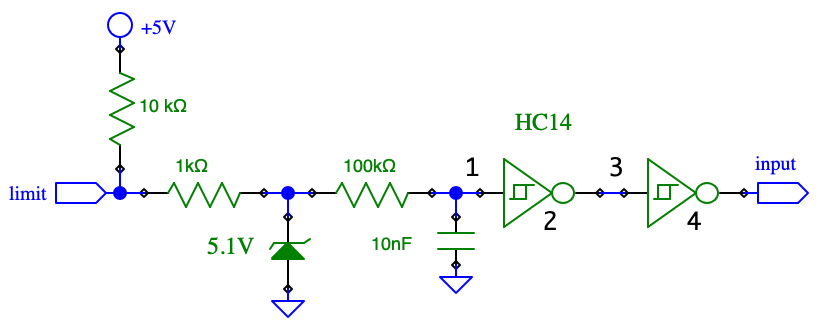
I design circuits. Anything this vulnerable is a very bad design, inappropriate for its environment. Is the schematic for the input circuit available? If a filter is to be added, I would add a zener diode to truncate any noise spikes at the inputs so they added as little as possible to the RC averaging that follows. What is the permissible delay from a real change in limit status to the time the interrupt is triggered?
Is there any input protection? Digital designers often under-protect. I once had to retrofit a design in which an unprotected input with a millivolt sensitivity was a few inches downwind in an air stream from a 25 kilovolt electric arc for coal ignition. Sources of noise are static electricity from air movement or abrasion, router motor and stepping motors. It is easy to run tests with router motor off and no air flow with no workpiece so the gantries are just going through the motions and only “cutting the air”. The stepping motors are the most likely source of noise however, because they are electrically connected to the longboard itself and there are lots of inductive spikes generated during stepping.
@paullarson 's comment to tie to ground is good for a test. +5 is also available and tieing directly to that as an alternative should be just as effective unless that supply is compromised.
I just took a look at some signals with an oscilloscope while a job was running: the stepping motor leads do not show excessive overshoot, so there’s less noise there than I expected. However, the +5 volt supply at the Xlim etc connector was out of spec noise-wise in my mind, though not enough that it should trigger 5 volt logic errors.
@saskia, any delay would be limited by the time it takes for a gantry to initially engage the switch to the time it’s gone too far, and this is dependent on how fast the gantry is traveling which can vary. When the inductive sensor trips there is about a 1mm gap (rough guess) between the gantry and the sensor. Lets cut that in half because you don’t want the gantry to hit the sensor. We also know that the maximum speed for the LM is 4000mm/min or 66.67mm/s. So, 0.5mm/66.67mm/s = 7.5ms max.
Regarding the design, I’m sure there is room for improvement and there has been some. I have rev 1.2 with no filtering on these lines. On later revs that was added. I wouldn’t mind seeing the schematic and .brd files, either. Also, no one intended for hard limits to be enabled with the X, Y and Z inputs disconnected.
I wish I had a scope. What do you have?
I have a battery-operated scope with about 100 MHz bandwidth that I got for under $200 off banggood (about 2 months for delivery, also got vernier callipers and my Neje 7.5W output laser from them). It’s a nice alternative to a fancy Tektronix when you need it sitting at 50 kV with respect to ground or you are worried about ground or power line noise contaminating the signal. Has bugs, but serves my purpose; trust, then verify… DANIU ADS1013D 2 Channels 100MHz Band Width 1GSa/s Sampling Rate Oscilloscope wi Sale - Banggood USA sold out-arrival notice-arrival notice
@CrookedWoodTex, That’s what soft limits are. You should be able to enable soft limits and leave hard limits off. As long as homing is working so that the soft limits have the proper starting point. I know that I said in an earlier reply to disable both, but that was kind of a shotgun approach. If you weren’t having soft limit errors, turn soft limits back on.
Thanks. I have been looking at those. There are quite a few offerings and I’ve been having trouble picking. I should quit reading amazon reviews.
Thanks! So the values in the little circuit with zener would be fine, about 1 mS delay in the filter, but doubling or tripling the capacitor size would be acceptable. I would use the +5 from the longboard, but add a 0.47 uF ceramic, a 22uF Tantalum, and a 470 uF electrolytic capacitor across the power to the inverter and keep the ground lead to the longboard fat & short.
On my longboard, the +5V is actually 4.6, dropping to about 4.3V during operation. The +12 (fan/misc) actually is 17V. I measured the pullup current on Xlim which comes out as a 36K pullup resistance. The +5V comes from the host computer and not from the local power supply. This could be carefully buttressed by an extra +5 supply, maybe from a powered USB hub or a special one local to the longboard. USB 3.0 specifies that a client device must be able to operate with a Vbus as low as 4.0 volts
The schematic for the Arduino UNO is available online as are the bill of materials and physical drawings for the longboard, but I haven’t found an electrical schematic relating the interface between the Arduino and the limit connectors. I did find a .pdf of the layout of V1.3 of the two-sided circuit board that hosts the motor drivers and the Arduino (in Sienci resources: Onshape).
I see no input protection or filtering of the sort that I routinely build into my equipment. I may design and build an small outrigged PCB that will connect directly to these inputs and provide the simple protection and filtering I described above. That would eliminate any noise IF that is the problem.
The issue has been present with CNCs forever. The hobby level machines typically don’t have the filters like you suggest. Some people never have issues and some have frustratingly persistent ones.
The noise coming from a trim router, especially a sparking one that needs new brushes can cause issues. Most of my issues were solved by moving my router and controller to separate mains circuits and keeping the router cable away from my USB cable.
A simple RC low pass filter is probably enough, but some might have to go through extreme measures to make sure everything is grounded properly.
Also, I bet you’ll see less of these issues come April/may.
HC14 + 9 resistors + 6 capacitors + 3 zener = about $5.
With motors and cables routed through the same drag chain, we are indeed talking about a lightweight industrial environment. Simple solution to minimize the extreme measures you mention; I don’t accept the idea that it doesn’t work right, live with it: that’s not acceptable design practice.
I agree. I’ve added low pass filters to limits on an old CNC mill that was converted to run Grbl.
You obviously know what you’re talking about… What’s the reason for the HC14 inverters?
The HC14 contains six inverters in one device so it can handle all three limits, driving the Arduino input with a robust signal. It has Schmitt trigger inputs: the hysteresis in the logic switching point eliminates the possibility of short pulses (stuttering) when the input is slowly varying as it will be with the RC filter in front of it. The very high input impedance allows a large resistor in series with the input. The zener diode truncates any large noise impulses which limits their contribution to the filter waveform and along with the large input resistor, protects the input from damage, such as from static electricity or connection to an out of range input voltage. The 10K pullup resistor could be increased to limit conduction from such a voltage into the +5 supply. The ( LJ12A3-4-Z/BX 5V M12 4mm sensing NPN NO cylinder ) inductive proximity switch sensor incorporates a 47K pullup resistor.
I had thi problem, just added a 0.1 microfarrad capacitor across the limit switch inputs on the arduino board. Solved the problem for the last 12 months