My design calls for asymetrical legs on each corner, and 6 drawers featuring elegantly curved drawer handles extending diagonally from each side. The drawer handles will be standing about 40mm proud of the drawer fronts and I’m planning to mill the slots (about 5mm deep) into the drawer front faces for the handles to sit in. I’m using Vectric V-Carve pro for my CAD program.
So far I’ve made the ends (gables) using my Longmill MK1 30X30. I won’t bore you with the process, but suffice to say the mold I used to form the asymmetric panels was done on the CNC. Same goes for the legs, with their dado slot to hold the panels in place.
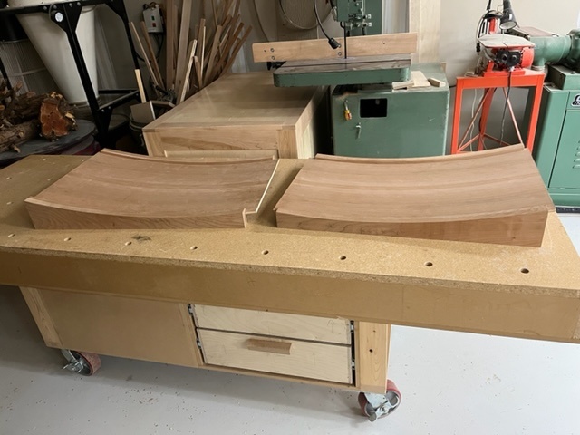
Here’s a photo of the gables, which I’ve laid on my mobile assembly table:
The panels were made oversize and still need to be cut to length. And of course there’s going to be a lower and upper stretcher on each of them, which I’ll also mill out on the CNC.
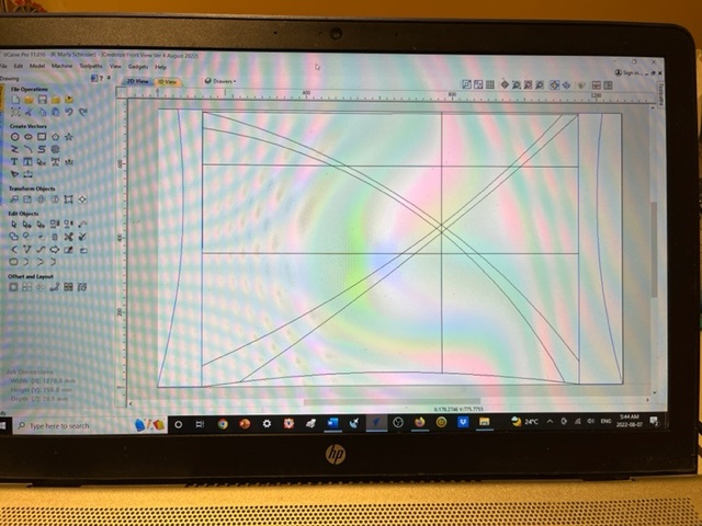
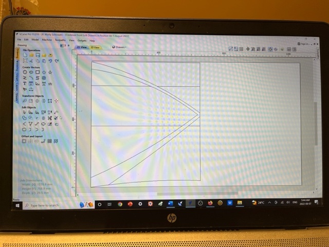
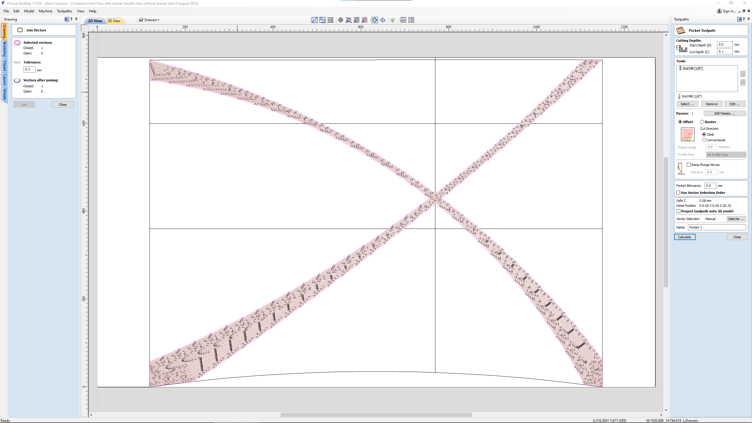
What I just can’t seem to figure out is the coding for the slots for the handles in the drawer fronts. And of course, complicating things is the fact that my CNC’s bed isn’t large enough to accommodate doing the entire front in one piece. So I’ve divided the job into a left and a right side. Here’s the left one:
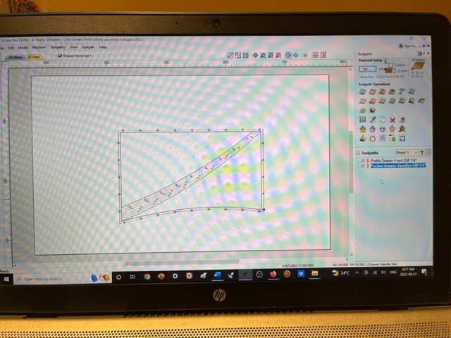
After hours and hours of head-scratching and still no luck at generating any g-code, I decided to make a simple drawer front. I drew the profile of a fascimile drawer, then made two simple arcs to act as the drawer handle slots. I was able to successfully generate the g-code. Here’s a photo of it:
@ApexWoodworks I could maybe help, but I don’t understand the issue yet. You have successfully carved a slot in the facsimile drawer. How does it differ from a real drawer? I realize that the real drawer will have two diagonals and the facsimile has only one, but other than that, how will the real ones differ?
An excellent place to go for help with this kind of thing is the Vectric forum. The regulars on there are very helpful and mind blowing in their knowledge.
Similarly, I am a Vectric VCarve Pro user, reasonably competent (at least I believe that), and would offer assistance were I to understand the question fully.
Can you either explain in more specific detail, or perhaps post the file here?
One candidate to look at is whether the vectors you are using are closed - the tool path won’t track as you expect if these are open somehow.
Andy, I’m not sure how much more detail I can provide that I haven’t already done. All I want to do is mill out the slot for the drawer handles (the sweeping lines that intersect). I can cut the drawer fronts out on my sliding tablesaw after the drawer handle slots are completed.
After that I’ll mill the drawer handles and glue them into the slots in the drawer fronts.
I’m unable to close the vectors, which as you’ve pointed out, is the crux of the matter here.
Michael, first of all, thanks for working on this file for me. I’d really like to know how you did it, though, so that I’ll be able to do it myself in the future.
I’ll see if I can send you a DM with my phone number so you can call me now if you’re available.
I used the node mode, n key, to cut the vectors in the center. Then I joined the vectors in the center. At that point the vectors were still open at the four corners. For those I had to draw a new line/curve over the existing ones and join those. At that point the whole vector was closed and the pocket was working.
Edit: To elaborate on the node cutting if you have never done it. N key toggles node mode. Left click on the node to cut, it turns red, then right click to open popup menu with cut option.
Thanks for the help and I’ll be sure to give you a number of photos of how it looks completed. But don’t think it’ll be any time soon as I’ve other more pressing projects happening right now.
@ApexWoodworks I guess that I didn’t ask the right question, Marty. At any rate, Michael has fixed you up. I just played with it and using node editing and join vectors with a straight line was able to close the “X” so that it can be pocketed. Just to say that there are many ways to skin this cat. Have fun.
As I am still in the learning phase of Vetric Pro. I came across Garrett with IDC Woodcraft on YouTube and He goes into detail on several videos about overlapping groves and forming tool path for proper milling/ removing of material. Here is a link to His latest video Why Do Toolpaths Sometimes Not Work the Way You Want? - IDC Woocraft - YouTube
He has several others about closing the tool path where lines intersect. From what I have read of Your post it would apear that from your design perspective drawing you are having issues with Vetric closing correctly the intersecting lines and either seeing them as one combined tool path or separate layers needing their own tool path.
I was able to figure it out - thanks as well to others here - and have already successfully milled the drawer fronts by dividing the job into 2: one for the left side drawers and the other for the right side drawers. It worked like a charm on my Longmill MK1 30 Sq.
@ApexWoodworks I’m glad that you were able to work this out, Marty. I was very confident that you would.
As the original issue has been addressed, I’m closing this topic. If anyone else has a similar concern, feel free to start a new topic, which will ensure that it is addressed promptly.