Lol, Grant. That’s usually my problem. And Jeff I’m sure you are not stupid. Simple mistake is all. And it’s fixable so don’t sweat it. Your turn in the barrel for the next person assembling theirs.
1 Like
Grant, do you think that will solve the problem with the lead screw sliding out? I know there’s a lot of torque going on but I can’t picture in my mind it coming out if it’s tight. I seem to remember one of mine being slightly loose so I took a big pair of pliers and squeezed the coupler so the slot was narrower. Took the set screw out and wrapped a shop towel around the coupler to keep from scarring it. It solved my problem.
Even with the bearing being backwards, that should not cause Jeff’s issue now that I think more on it. Think of it. The coupler should be a solid link between the motor and the lead screw. You could take the bearing out altogether and the solid link would still keep the motor attached to the lead screw.
So, Jeff, I don’t believe that we are there yet. Since you are sure that the coupler is coming off the lead screw end and not the motor end, I would go back to my earlier advice. Take the coupler off altogether and try it on the other end of the lead screw where you can get a good look at what is going on.
If you tighten the set screw and can pull it off the lead screw, try Heyward’s fix. That is preferable than trying go close the coupler by really reefing on the set screw. You could strip the threads in the coupler or the head of the set screw.
1 Like
Hi Team,
The flange bearings being backwards were definitely part of the issue. I took all three axis apart and ensured they were set up correctly (which is completely logical in the light of day… I guess that’s a good lesson about staying up to “finish” a job at 1am).
There was still a problem with the V1 couplers. Not sure who raised it first, but you do need to back those set screws out further than I expected. I think I was so focused on not backing them out so far that you lose the set screw (once bitten, twice shy from other work) that I failed to get it out quite far enough. Even after I fixed the flanges and everything seemed ok for a bit, then the right lead screw slipped off. Having already re-set the left one, I had witnessed what backing the set screw off a bit more and really ensuring the lead screw fully seated felt like. I carefully re-did the right side and it’s been fine since.
I just finished aligning my feet and I’m almost ready to draw something (I figured I’d use some sharpies on bristol board first to try things out, before adding the cutter in). In the mean time I went to take the bit out of my Makita (which I’ve had for a while, I have multiple bases for it) and I discovered that I could NOT get the collet nut off. Like it took extreme force. I took it out of the mount and put it on the table and used both wrenchs that came with it and I could not get it off. It’s been tight in the past but this was extreme.
Closely inspecting it, it seemed like there was a ring of dust packed in around the 1/4" bit that I had in there. I shouldn’t have stored it with the bit in. I ended up having to use a 22mm ratcheting wrench along with the small spanner it comes with and I finally got it to let go. Then I inspected the inside of the collet shaft and there was a fine layer of dust and debris built up in there. I got a q-tip and (dry) cleaned what I could out. Seems to be better. If you haven’t checked yours in a while, might be something you want to look at.
Thanks again to everyone who helped me fix my silly mistake and guided me on how to set the couplers. The next thing is trying again to understand exactly what Chris is saying about how to properly tension the wheels. Something still doesn’t feel right there and I seem to have chipped the edge off one of the wheels (eek). @chrismakesstuff can I buy an extra bag of wheels?
Back to the shop to adjust the wheels again and then strap a sharpie to the router shaft and take this thing for a test drive!
-Jeff
1 Like
Good job Jeff. Not sure how you chipped a wheel. They are pretty hard. If you need another you can buy them on the Sienci.com web site. Look under store tab then extra parts and scroll to bottom of page. It shows multiple wheels but I believe the $3.20 CAD price is for 1.
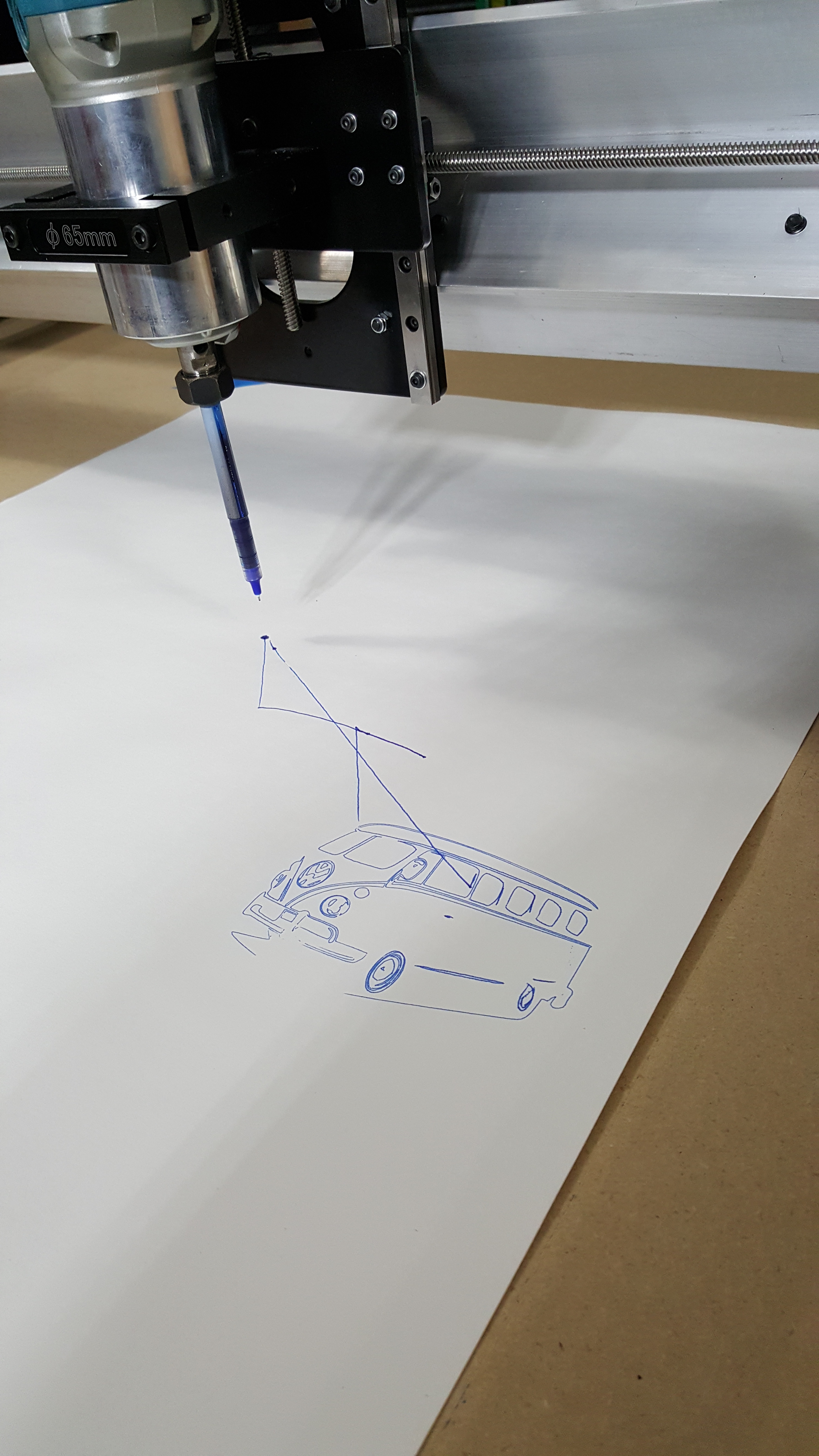
It lives!
Since I don’t have a pen mount I played around and discovered I could sort of hold this particular pen in the 3.8" collet for the Makita.
My fusion 360 is pretty rusty at the moment but I managed to import an SVG of an old VW bus and get it to draw it. I had a few issues with defining my zero and getting started (very easy to break the pen tip and my board isn’t completely level yet of course) but I think it turned out pretty well for my inaugural Hello World style test. Now to make some chips!
Thanks again to everyone for their help. For my next trick I think I’ll chuck up a small diameter bit and cut the outline of the work area in to the wasteboard manually and them I’m going to ponder how and where to put my dog holes and maybe even cut some dog holes in the 2x4 I’m going to lag in to the wall to support this beast vertically to get it out of the way.
For my second project I’m going to whip up a pen holder out of wood. No 3D printer here at the moment…
-Jeff
1 Like
That’s a good start. You’re on your way.
That is precisely why I’m considering making a flat on the shaft.
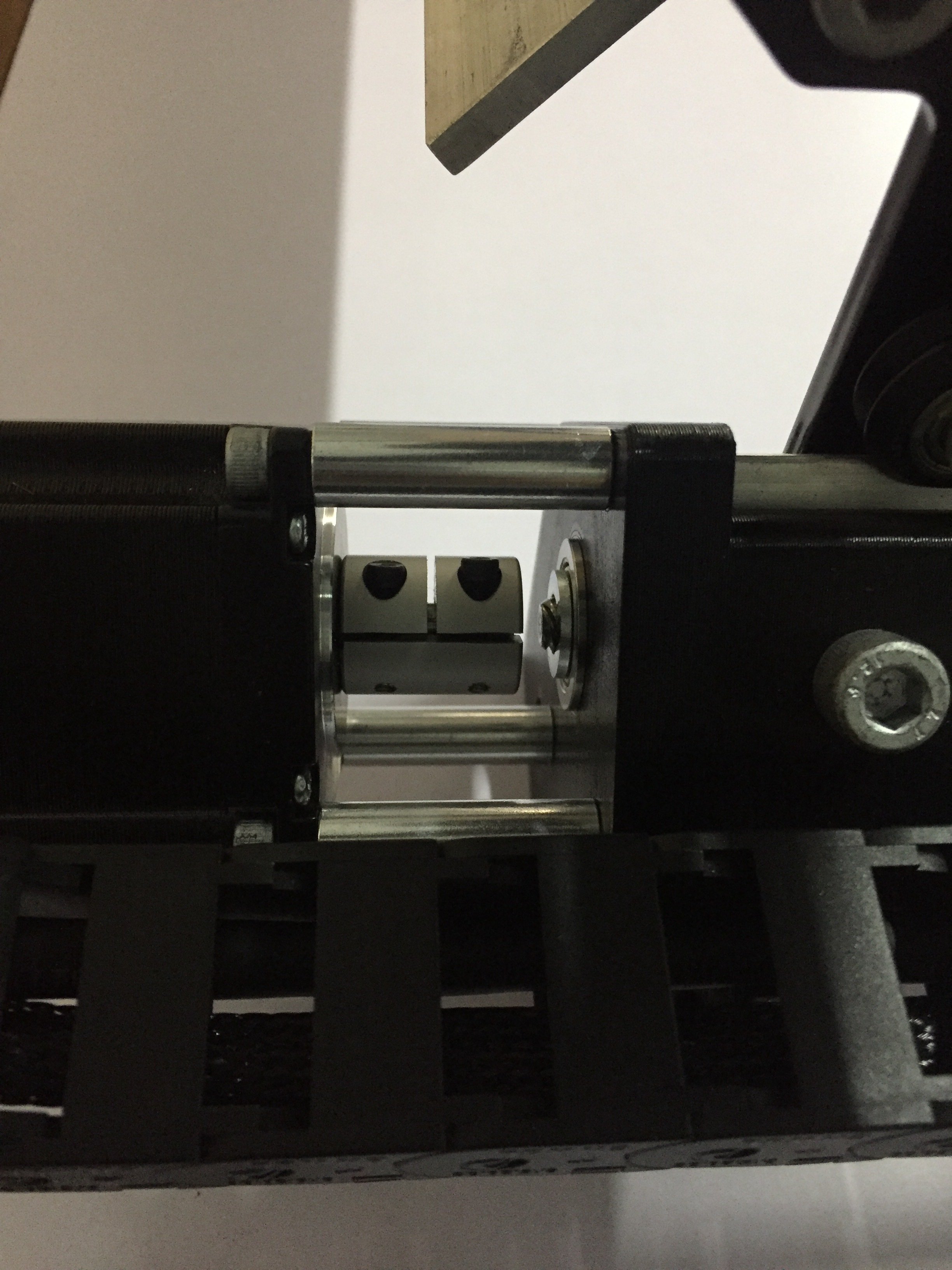
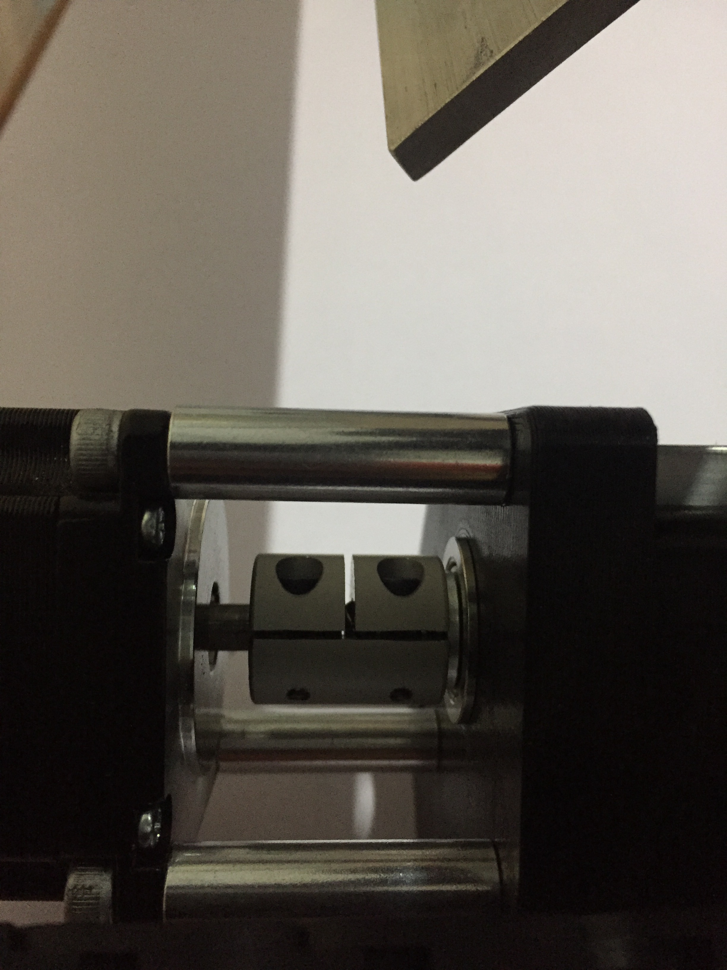
Hi, I just setup my LM but get a similar problem. My left Y screw comes loose when i sent it all the way to the back. Coupler tight as i can get it.
![image|375x500]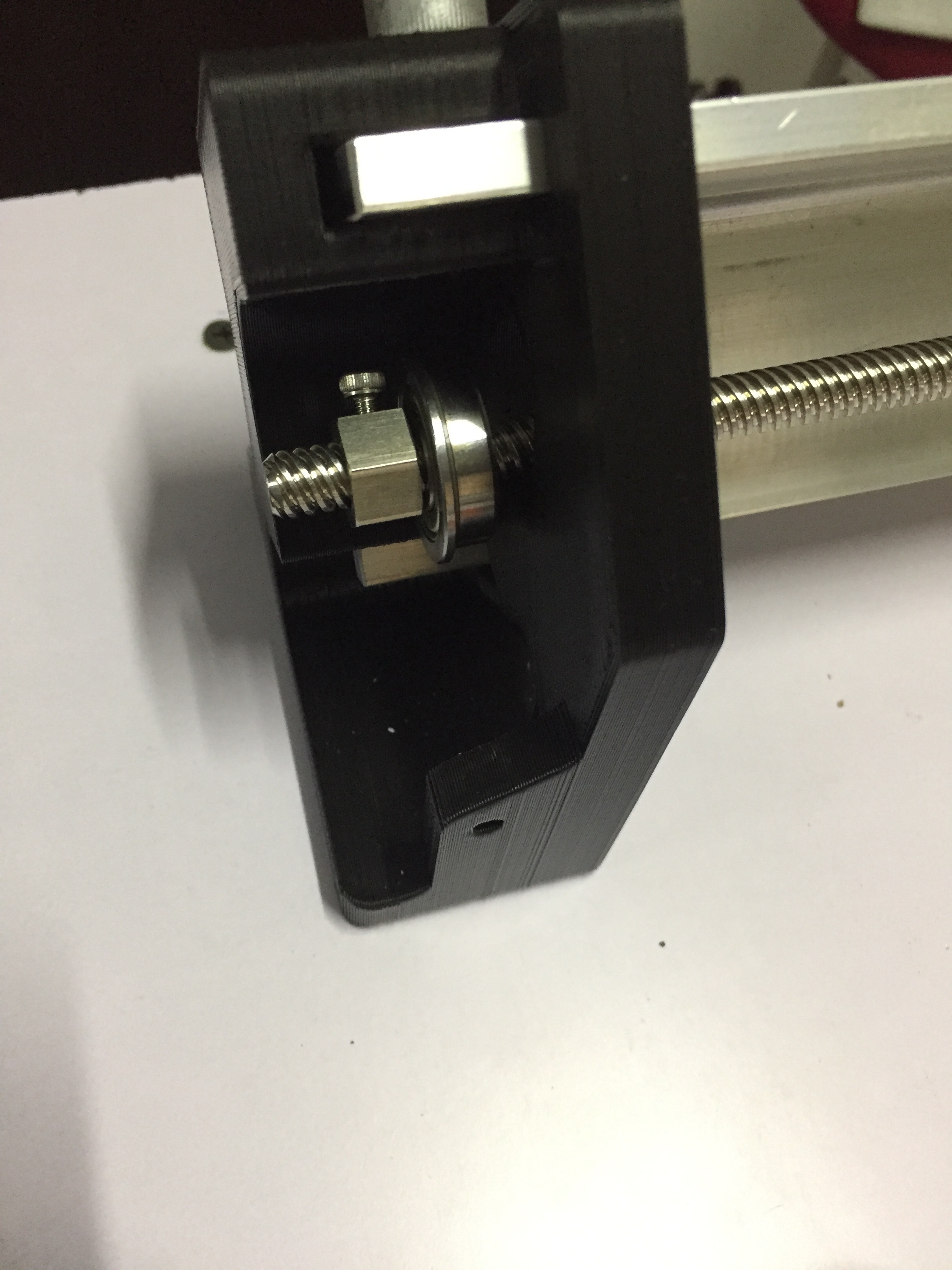
@Raj11 - The only problem I see here is with the coupler being up against the motor. Once you push the lead screw in all the way into the coupler and tighten, loosen the motor end and slide the coupler against the washer. This will leave a small gap between the motor and the coupler. Tighten both coupler set screws. Then, if necessary, adjust the nut on the other end of the lead screw. Also to make the coupler tight to the lead screw I remove the set screw, insert the lead screw into the coupler. Then I look into the set screw hole and line up a gap (between ridges) and then insert the set screw and tighten. This, to me, puts the screw pressure between the ridges and IMHO makes for a tighter fit. Hope this helps.
1 Like
Thanks for the reply.
Forgot to mention that the picture was to show what happens after the screw gets loose. I also just tried your solution but get the same problem. I really turn the coupler screws tight. When i pull the leadscrew it stays in place. Its only when the x is sent all the way back to the motors that it comes loose.
The picture shows how it sits before coming loose.
@Raj11 - Hmmmm? One last thought. Is it possible that your backlash nuts are too tight. When you run your axis all the way back (or front) you should hear a thump thump kind of sound as the backlash nuts slip over the lead screw threads. I don’t know if it’s possible but if they are too tight they couldn’t slip thus causing the rotation to continue until the lead screw pulls out. Follow the procedure in the assembly guide to check. This is a WAG (wild a** guess) but worth checking.
I just switched the left and right coupler. I don’t know how but it’s holding up much better now. But after a few tries pushing the x back i can see the left Y screw starting to get loose again(not completely like before).
Something else i noticed is that the left motor, when i took it out to switch couplers, i can turn by hand but the right one not. The left motor also makes another noise compared to the right motor. Like it’s not turning smooth.