Looking for info on homing/limit switches. Did any of you guys with beta units use them? If so what kind did you use and where did you get them? Where/how did you mount them. Personally I think they are a necessity to keep from damaging the equipment. Looking at different ones online they run the gamut in styles and prices. I did find the micro versions somewhere for about $30US for 6 of them. Some of the videos recommended using 6 switches instead of just 3 so you cover all of the directions. Also most of the tutorials I watched recommended using the Normally Closed versions instead of the Normally Open. I see that a lot of them can be used either way depending on connections on the switch. I know that you can set soft limits but I don’t think I could put much trust in them. Any help appreciated.
Thanks for the info. I’ll check out the OMRON switches. Definitely want sealed ones for dust protection. I’m not sure about opto vs magnetic but I’ll research that too.
No no one that I know of in the Betas used them at all. I personally never found a need for them. You can’t damage this machine by going to the limits of the rails. Also through the years all these machines have been developed Chris and Andy also have never seen the need for them either. That isn’t to say you can’t use them. Its up to each one.
I’m pretty sure I damaged my machine by running the Y axis all the way forward. The first thing to hit was the anti backlash screw. It’s now stripped and I need a new delrin block.
You cannot damage it by doing that. The delerin block would not have been effected because the motor stalls. This prevents damage to the other components. Now if you think the blocks are damaged you can order more on the site. They are cheap enough I think they are $12 for the 5 that are on the machine go into the shop. They are in the extra parts area. Its not that hard to swap them out.
I got the replacement and swapped it out. The threads on the old one are stripped - they just crumbled away when I removed it. I looked at the cad model and I’m sure that if you use a 20mm bolt instead of the set screw, then you run the risk of that screw head slamming into the end stop, or getting deflected into the hole where the bearing resides. I think the force from that stripped the delrin nut. The screw had been deflected downward to where it was scraping on the lead screw. Yes I know the motors will stall but not before applying some force.
Bottom line, I’m using the set screws, so it can’t happen again.
Dave
Good to know. I have run my into the end and not had that happen so found it weird that it caused any damage is all.
I think the original design suggested the shorter screws but in the assembly, they did suggest the longer ones for ease of use. I see your point tho. I have hit this limit too and I think the shorter ones would be better.
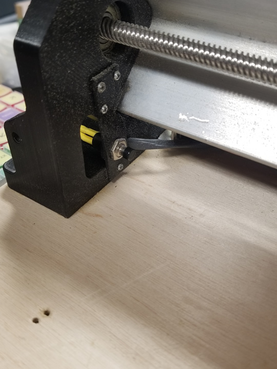
I added homing switches to my long mill. I used panel mount, momentary contact, normally open, push button switches that I found on Amazon:
I 3D printed brackets and those files can be found here:
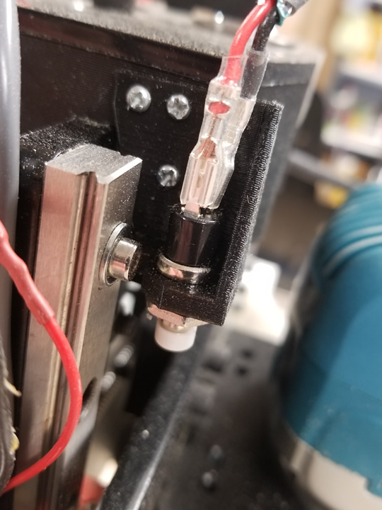
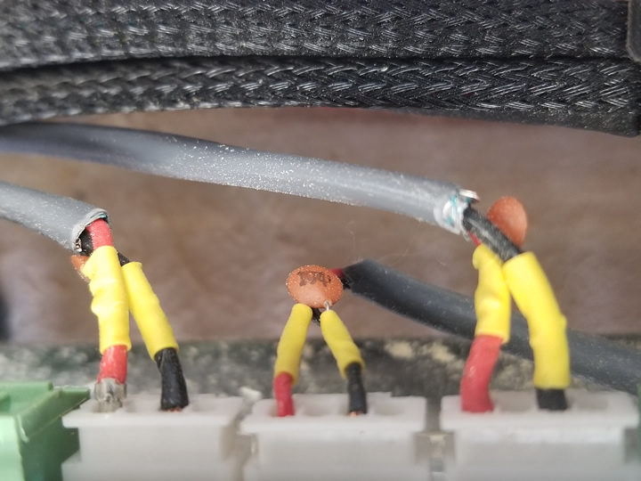
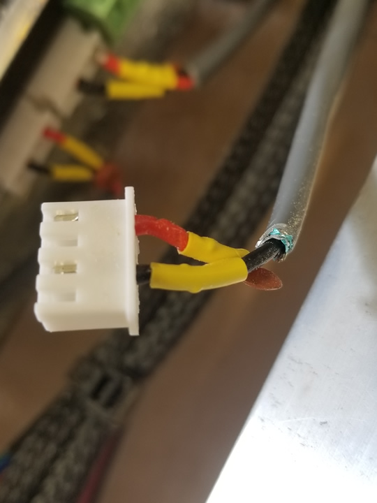
i used 2 conductor shielded security wire from Home Depot, JST-XH connectors and soldered a .1uF capacitor across the inputs to the longboard.
Another good mod, Philip. I understand that the Mill cannot be damaged by running it to its extents, but the sound when that happens still gets to me. Also, it throws off the xyz 0 in UGS every time that I forget and run the Mill to its end in X.
Where do the wires from the stop enter the Mill controller? You are clearly more competent with electronics than I am, so I for one would be grateful for more details.
Thanks Grant. My inspiration came from the instructions by Troy Barbour on the Mill One Open-Source page. Homing switches mainly give you the ability to return to known locations relative to the home position. This is extremely useful..
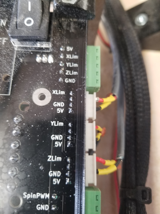
There are 2 connection options on the longboard. Both are clearly marked xlim, ylim, zlim, and gnd. There is an included connector at one end that has a screw terminal for each axis and one common ground for all axes. The problem with this connector is that it is difficult to add the .1uF capacitors that are needed for each axis. the second option are the three white jst-xh 2.54 mm connectors that are also clearly marked, one for each axis. This gives you much more room to attach the wiring and capacitors, but the female connectors that you need are not included. You can get them on Amazon either already made up with lead wires or you can buy a kit that will allow you to make up your own connectors, which is what I did. Once you figure out the crimp tool it is pretty easy to crimp on the pins and build the connector. Just be sure to get the pins into the right position on the connector. signal is on pin 1 and ground is pin 3.
Without the capacitors I was getting false alarms. I found it easier to strip some insulation off of the wires going into the connector to solder the capacitor on rather than trying to crimp it into the pins.
Just what I needed, Philip. Tks much.
Sorry if this is a dumb question. I am unfamiliar how capacitors are use or wired in. If you don’t mind can you give me a bit assistance with which leads (positive and/or negative) would be used to wired in the capacitors?
Capacitors can be polarized or unpolarized. I used unpolarized capacitors wired across the input and ground of each switch. I never considered using polarized capacitors but maybe I should have. I was following the Long Mill documentation 5.0 Advanced on adding limit switches.
“It should be noted that it is very important to shield and filter noise along the lines with the limit switches, as interference can cause the limits to trigger erratically. We have found that placing a 0.1uF capacitor across the input and ground for each limit helps to prevent errant triggers.”
Since there is no mention of polarity, I just assumed that polarity doesn’t matter.
Thank you I will look at that document.
I just finished putting it all in action. It works great thanks for the post and advice.
Great job!
I would love to know how repeatable these push buttons are for you, or for any others that have used them?
If you put dial indicators on the axes and check what the deviation is from 0, on multiple home cycles.
These are simple and small. I was debating to use Omron style micro switches with a lever arm, but if these are good  …
…
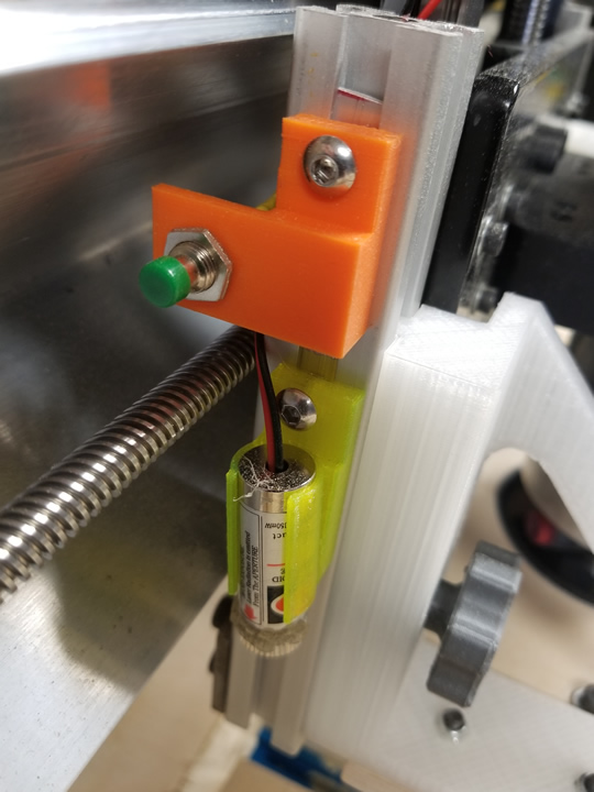
Oh btw, what do you use that laser for, on the Z axis?
Great. I am glad it worked for you.
I have not tested it for repeatability on multiple home cycles. I wan’t going for dial indicator precision. I want to be able to do rapid movements to specific positions on the work surface. I am still learning gcode for CNC and am experimenting with the macros that I need.
The lasers are pointers to aid in positioning the router bit over a particular spot on the work piece. I took the instructions from the Mill One Community Open Source Page, which is where I also got the instructions for the homing switches.
I used the 2020 extrusions for the dust shoe to mount the lasers. I printed the mounts on my 3D printer. I am working on redesigning the mounts and I will put my files up on thingiverse and post a link when I have them ready.
Thanks for the reply sysimgrp. Hmmm…those laser cross hairs are an awesome idea!
I’m going to look at that again once i have the rest of the machine running.
Thanks again