Hello Moosa! I don’t use Carveco or SketchUp but your post made me wonder how I would go about making that with a v-bit.
I think that my approach to solving it is probably more important than the actual software used so I will share my take on this done with Vectric and OpenSCAD.
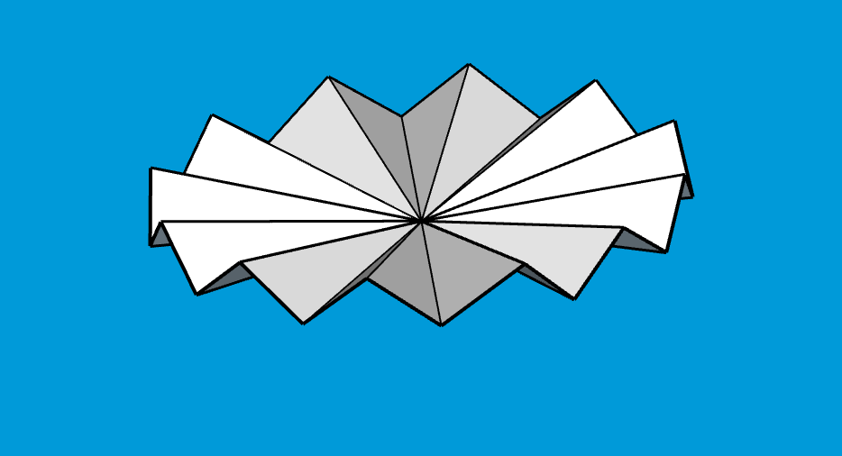
So your model appears to be made from a center point with a circle of 24 points around it that alternate between some +Z and -Z, up and down around the circle.
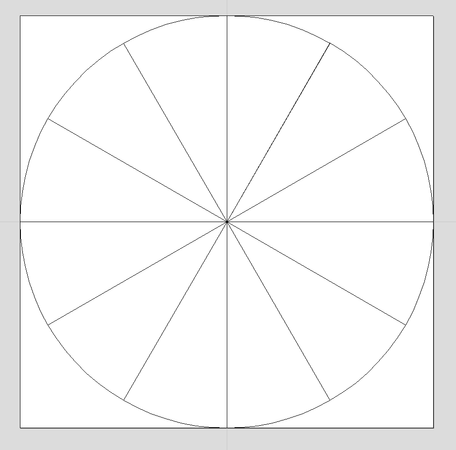
I set my material up to be a 100mm x 100mm x 19mm thick and started with a 100mm diameter circle split into 12 sections because a v-bit will create 2 sides and we need 24 sides.
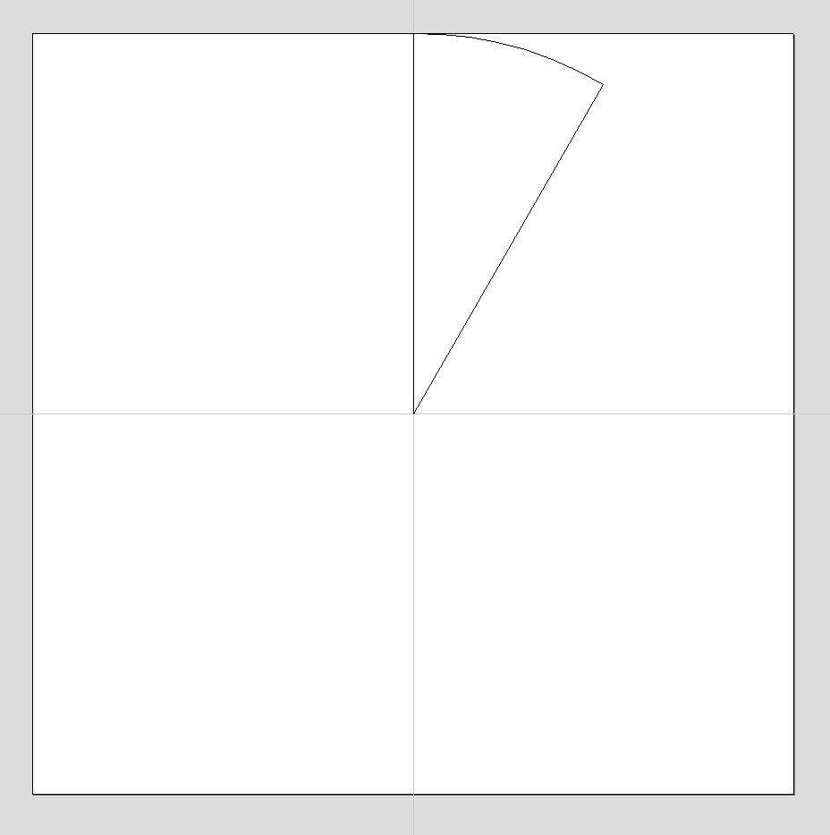
I then isolated one piece of the pie and made it into a closed vector.
I used the rotate copy function to make 12 total copies rotated around the center point. This of course looks exactly like the first image but is made from 12 closed vectors, each of the center lines has a copy that is part of the next piece of pie.
This allows you to v-carve each section of pie. I used a 120 degree v-bit in my simulation because I was worried about how deep the carve might be, which of course will depend on the diameter of the circle used and the angle of the bit.
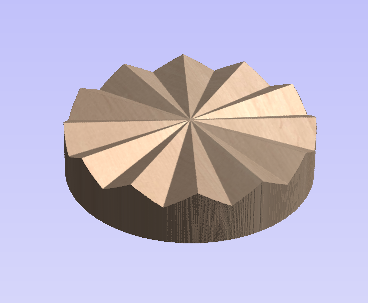
I got this as a result and if we then make another centered circle at 75mm diameter and cut that we can clean up the outside edge to more closely match your model.
This is starting to look pretty close but the center point is on the surface not midway between the outside points in terms of Z.
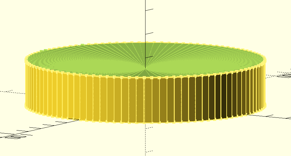
To fix this I created a model in OpenSCAD, not that the software matters, that is a 19mm tall cylinder, 100mm in diameter, with an upside down cone removed from the top. The height of the cone was half the depth of the v-carve. Vectric will show you the max depth of a carve, hopfully Carveco does as well.
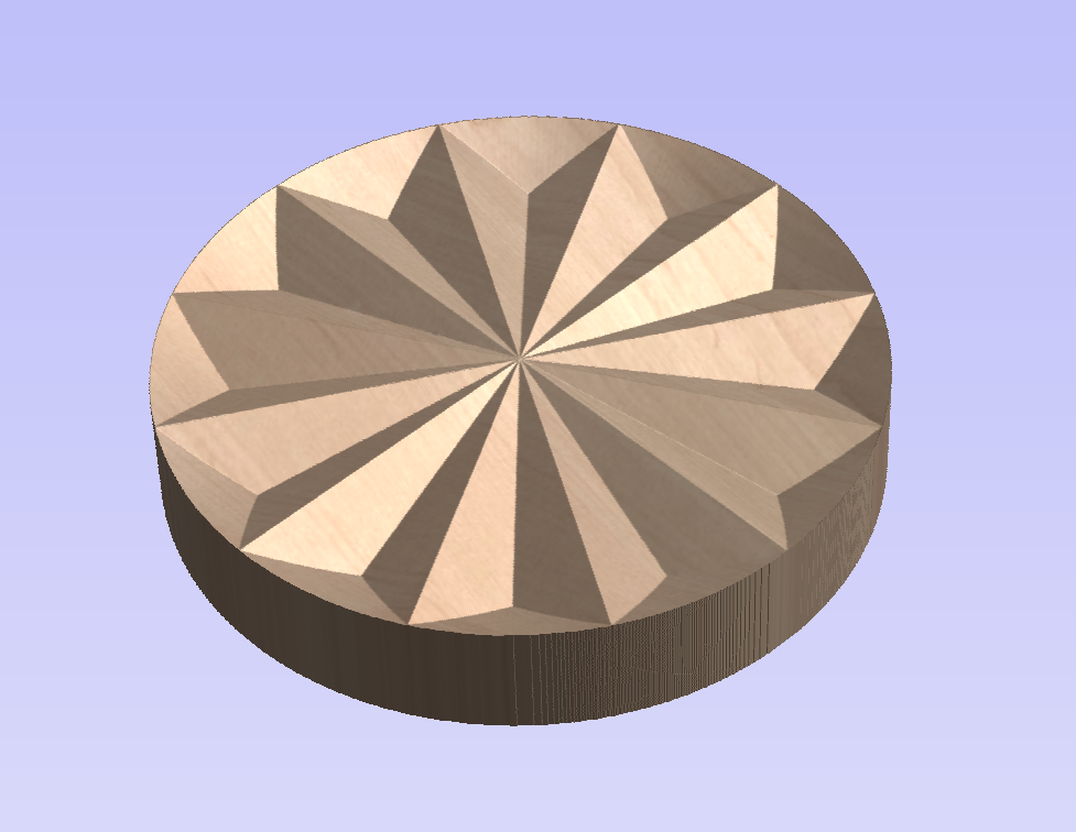
I then brought that model into Vectric and there is a ‘Project tool path onto 3D model’ feature that I used. Again maybe Carveco has the same thing with a different name. This feature in Vectric changes the 2D vectors that defined the carve to follow the contour of the imported model.
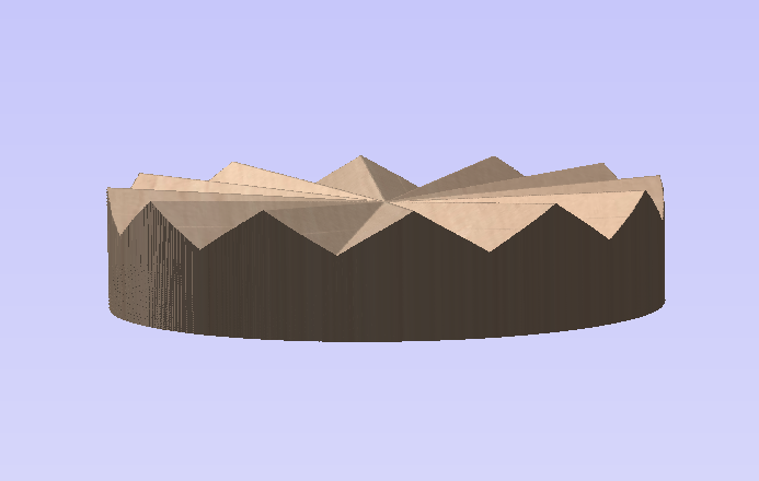
This final result is a pretty good representation of your model IMHO. Using a v-bit will of course limit the angles that you can use to make your shape but should leave nice clean lines, I would think.
I hope this helps you to create what you want.