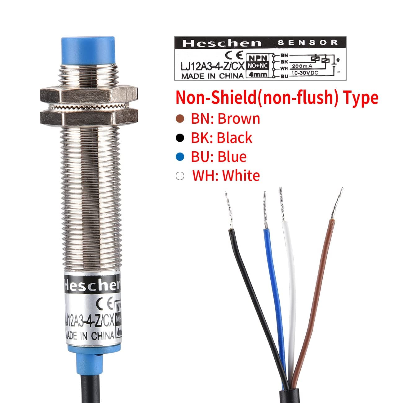
but the instructions only show how to wire a 3 wire sensor and doesn’t really explain which wire is which, so I’m slightly lost (see Technical Manual - SuperLongBoard where the red is VCC, the black is limit and the blue is GND but I don’t have any wire marked ground in my sensors, is that supposed to be the negative terminal?).
The second problem is I would like to use the jst connectors, but I can’t figure out what’s the right metal connector I need to crimp on the wires to put in the connectors. Could someone help me find the right part (ideally on Amazon for ease of shipping but any other store that ships to the USA will work as well).
Hi Lucky,
First, your inductive sensor is fit to be used with a vcc between 10V upto 30V. I take that you know that the SLB is set up to have a vcc at the Limit switch connectors to be 5V. I then assume you know that you need to alter the boards vcc output to be 24V by removing R9 and solder bridge the pads for R10.
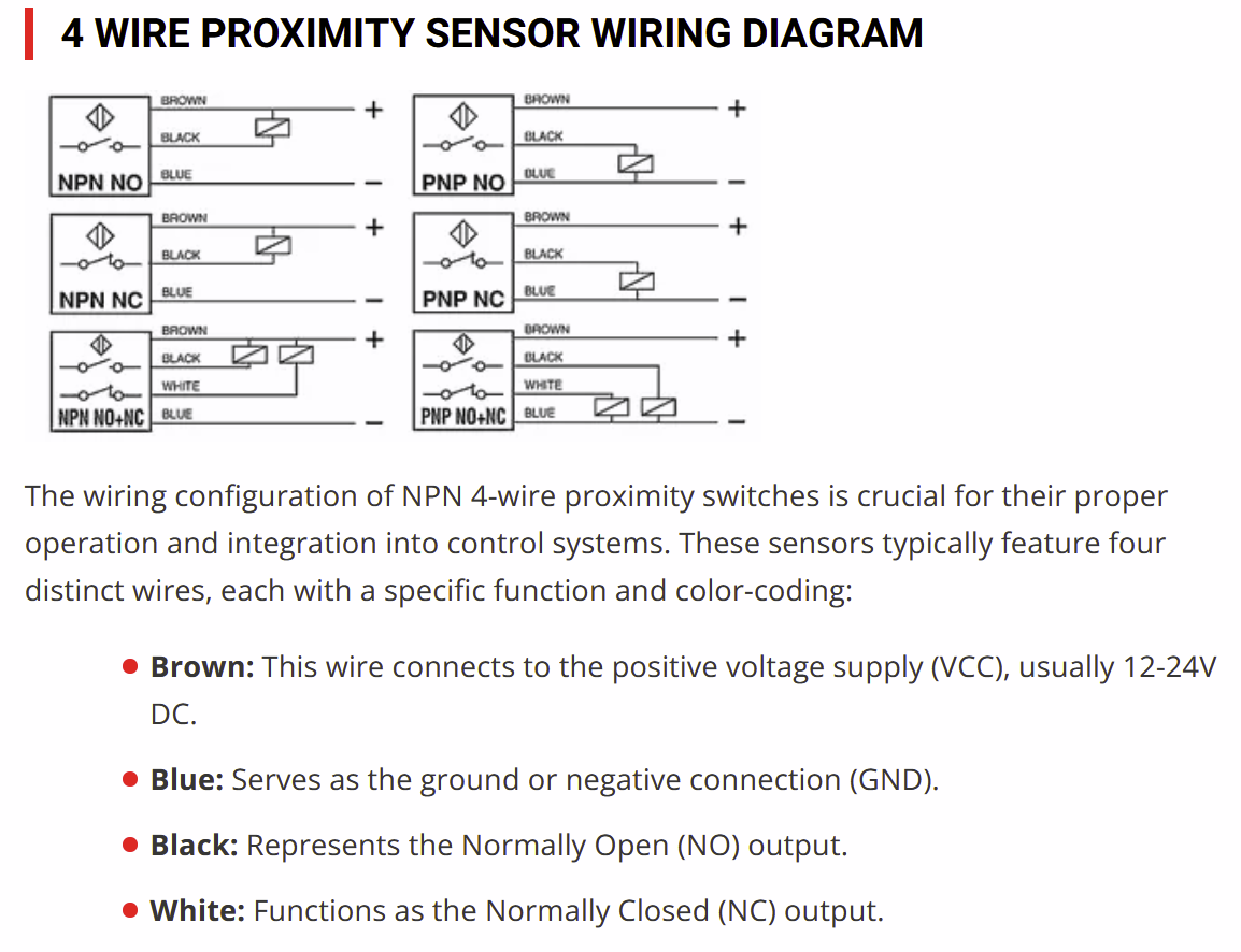
Your inductive sensors are fitted with an extra wire because it switches NO and NC. Since you can invert the input in the firmware tool (#5), it really does not matter which one you choose, as long as you stick with that choise for all your limit switches.
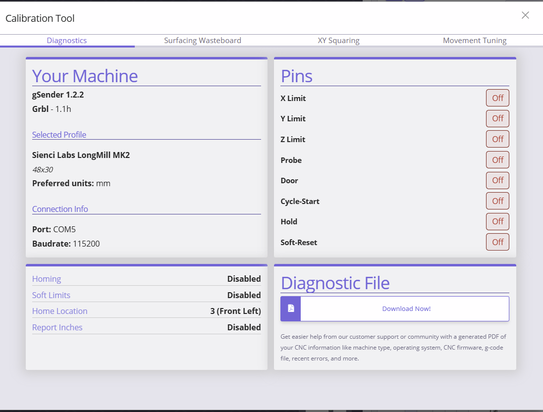
I too have been playing around with self sourced switches and found great use in the calibration tool where you can see if a sensor is active. I did this by wiring the switch to the green Limit switch conector and looking at the pin detector in the calibration tool diagnostics tab.
I think it might be wise to setup your switches wiring on the green connector too and test the machine working with your sensors, before crimping them onto the white connectors.
Measure twice, crimp once.
There is a connector list found here, it might give you enough info to figure out the right crimpables for the connector you need.