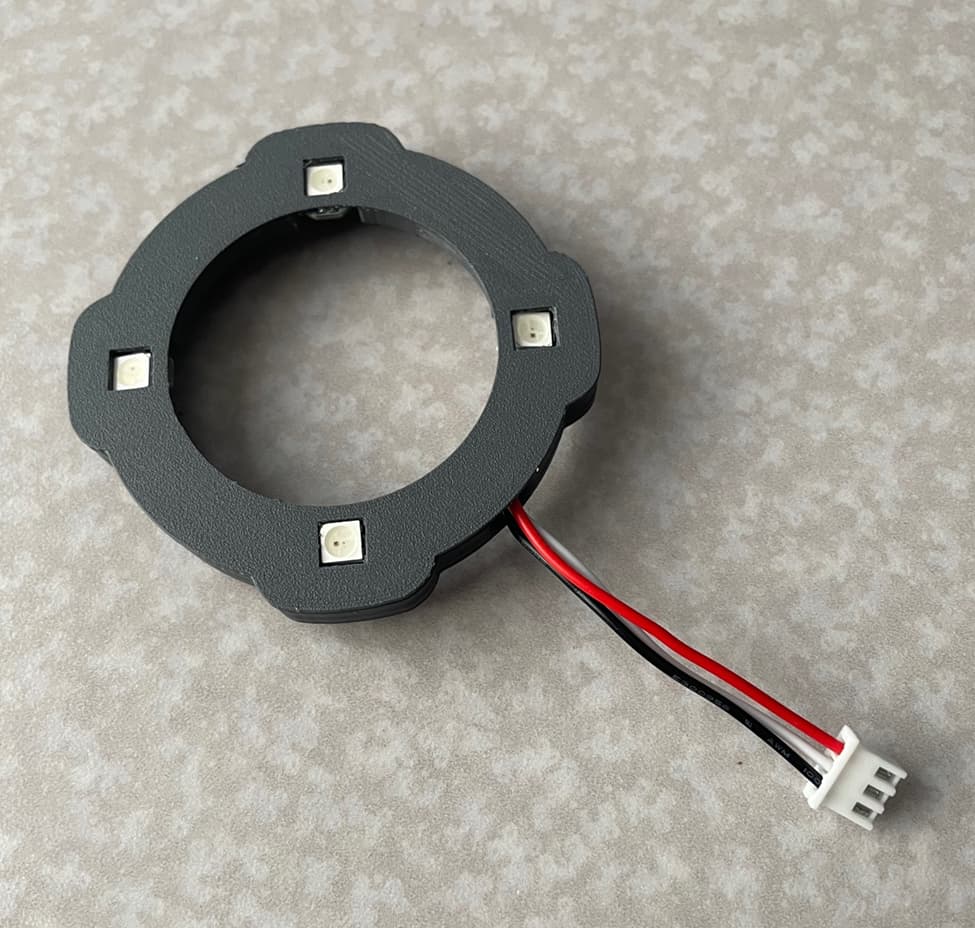
Not being able to find a Ring LED that fit my Sienci 1.5kw spindle the way I liked, I decided to design and make one of my own as follows…
It’s a snug enough press fit onto the bottom of the spindle that there is no need for any adhesive or tape to keep it in position:
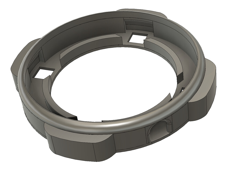
I designed it in Autodesk Fusion, sliced the file in PrusaSlicer and then 3D Printed it on a Creality Ender 3 v2 Neo. If you want to make this yourself, I have attached the .stl file (at the end of this post) so that you can slice it for your 3d printer. Just remember that this ring will only fit Sienci’s 1.5kw spindle.
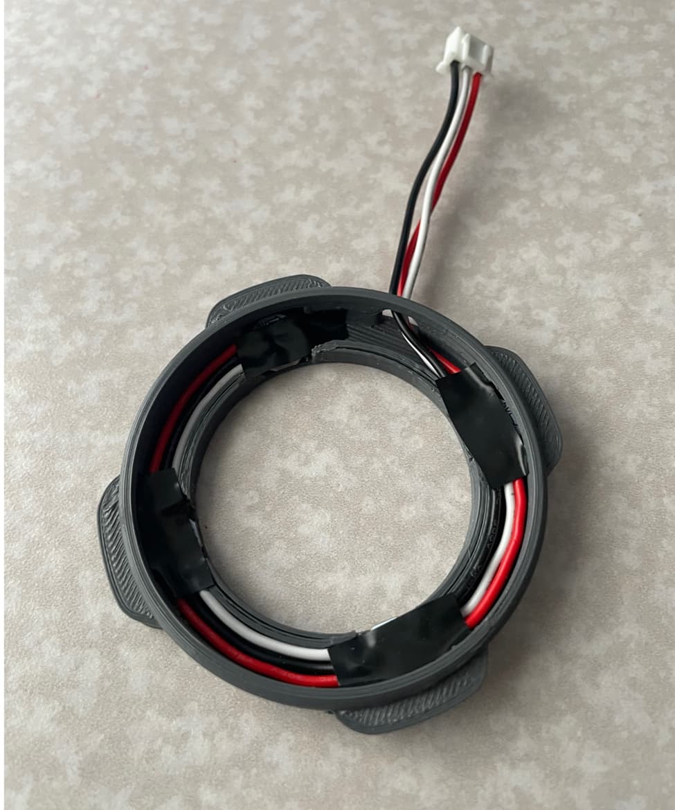
The wiring is very straight forward. Red goes to the 5v pad, Black to the Ground pad, and White to the Data pad. Ignore the fact that I somehow switched the black and white wires after the 2nd LED. The connections are still correct, so all was good, and I didn’t feel like redoing them ![]() :
:
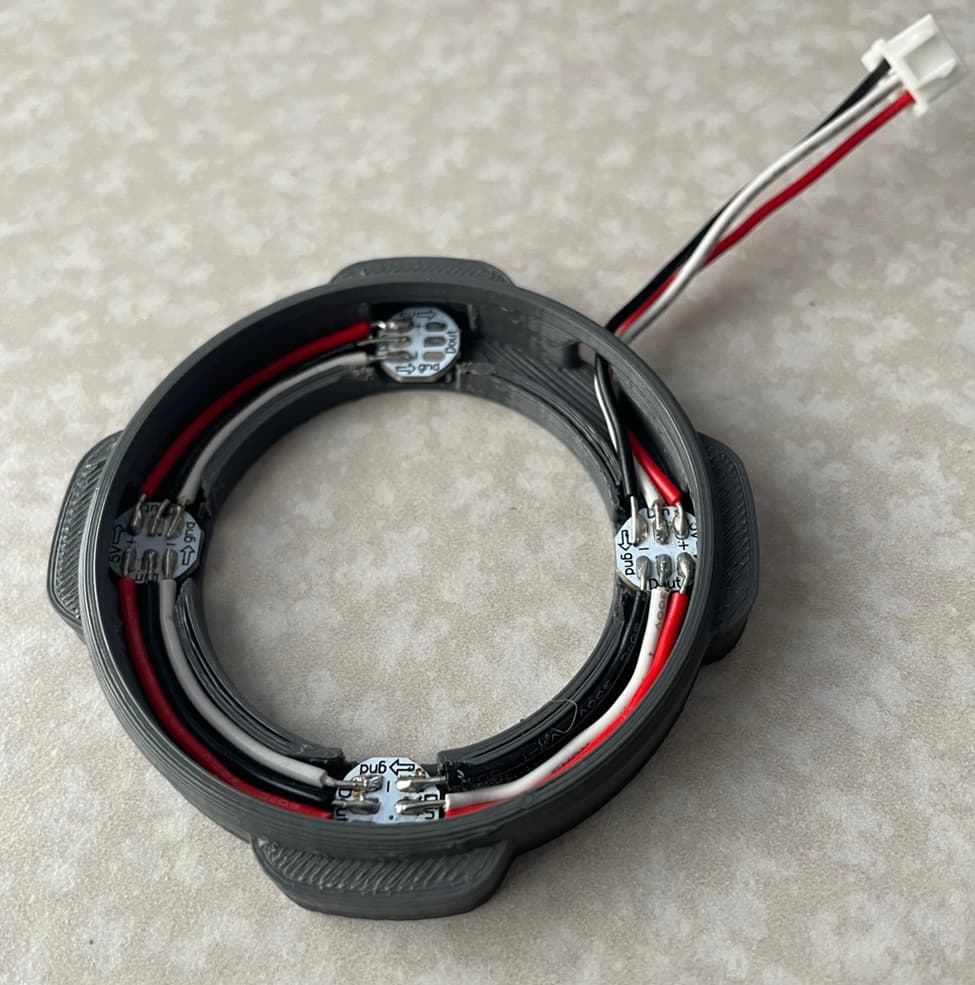
I initially planned on making a flat ring to place on top of the exposed solder joints but then thought hot glue might work. I eventually just settled on some strips of electrical tape:
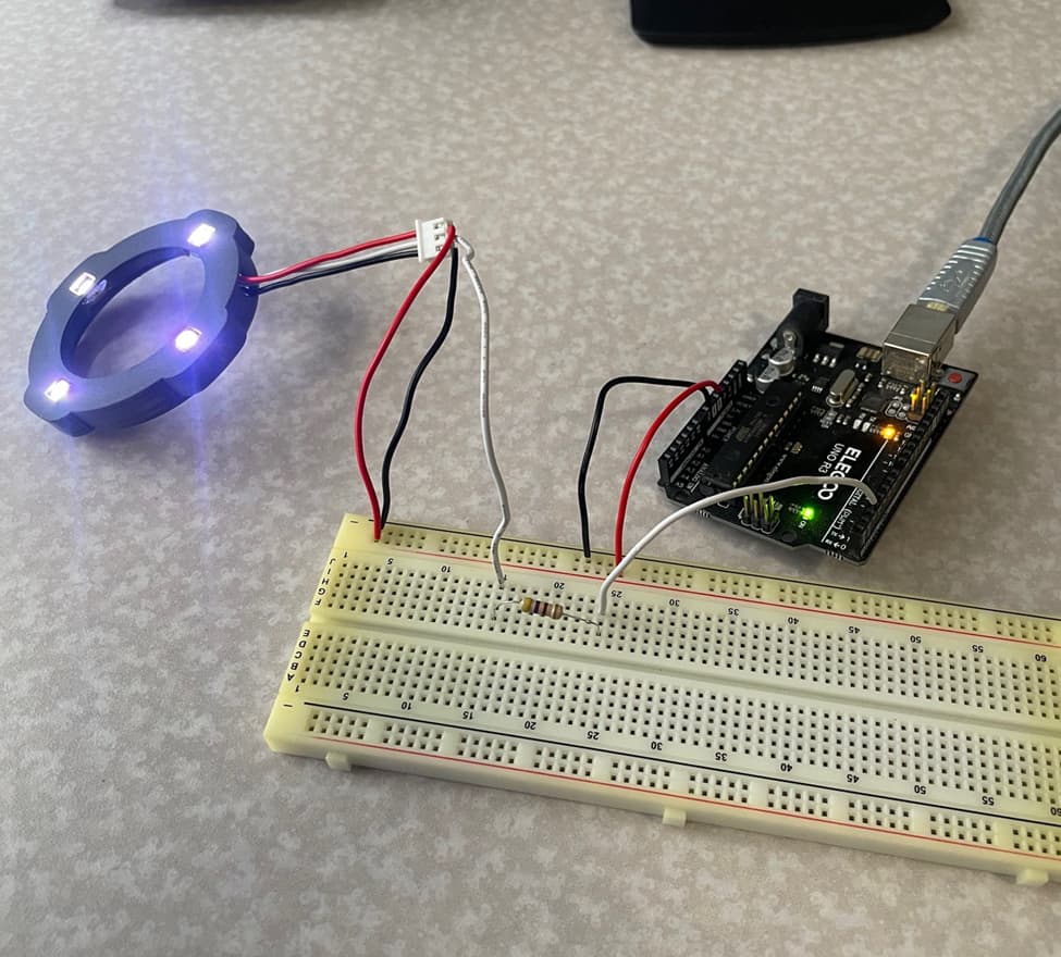
Here I am testing the ring using the Arduino from my old Longboard:
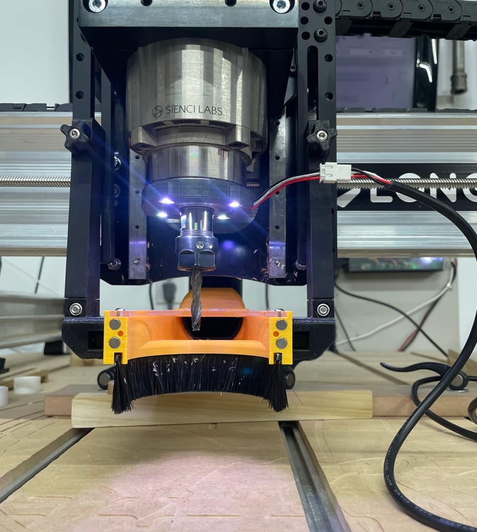
And here it is pressed on to the end of the Spindle and hooked up. I hadn’t run the wire through the drag chains yet:
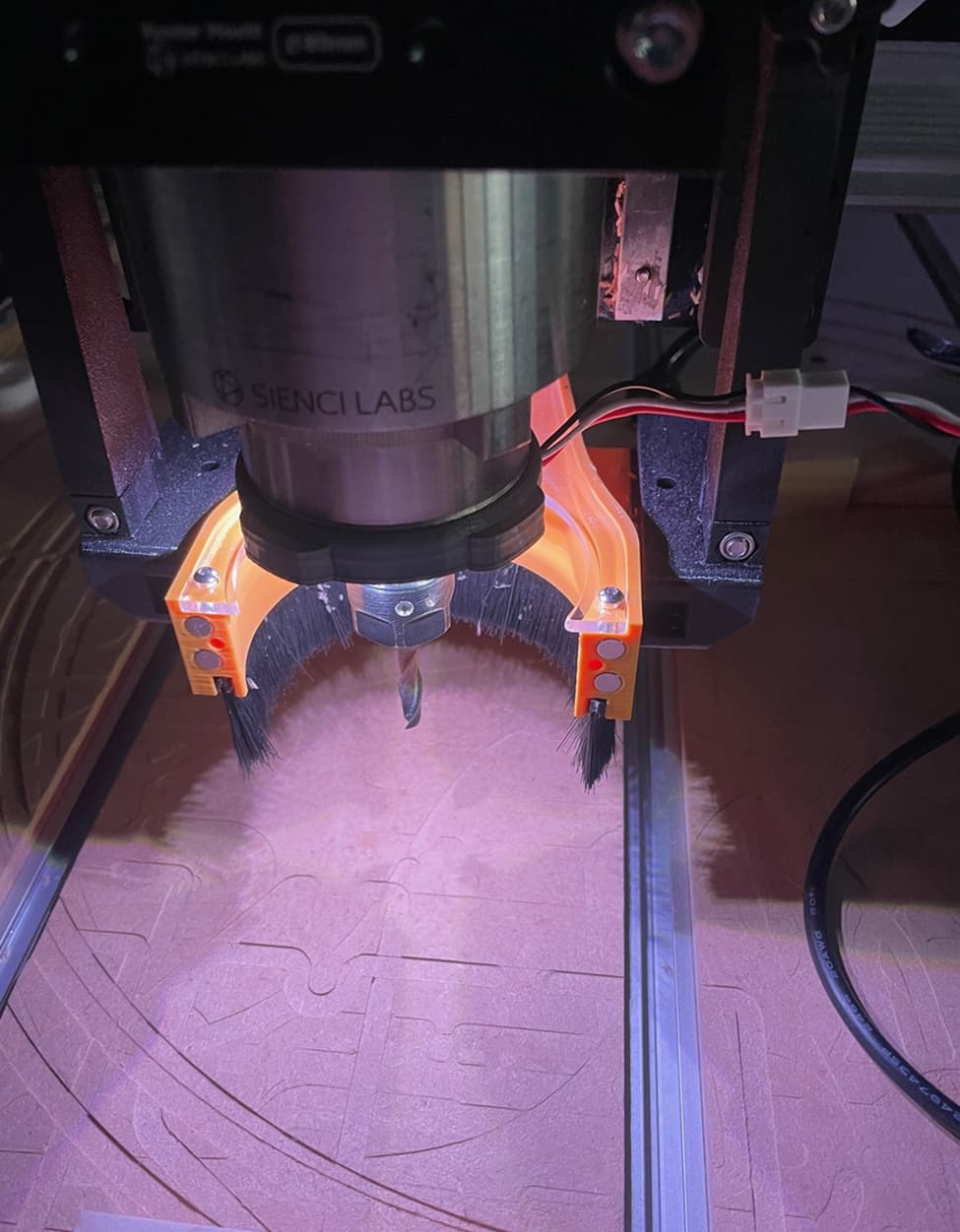
This is a photo with the lights in the shop turned off so that I could show how much light is being given off by this setup:
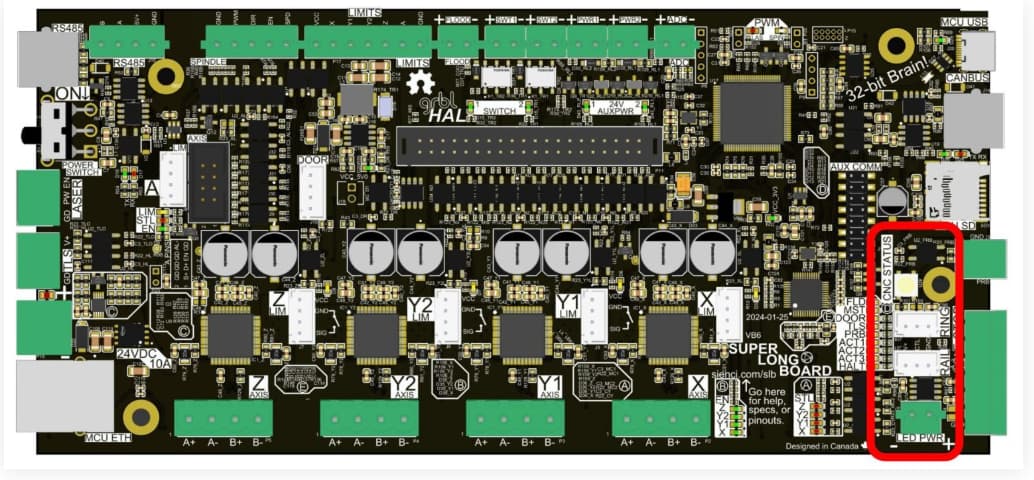
Check out the LED Strips section of the SLB’s Technical Manual for lots of information about installing extra LEDs on your Longmill/Altmill.
The one thing that felt odd to me was that the Ring LED port causes these LEDs to be the same colour as the main Status light on the SLB. That meant that when it was normally running a job, the LEDs would be green. Maybe that makes sense for an extra LED strip on the underside of the X rail but for the Spindle ring I think lighting up the cutting area with white light is more beneficial (@chrismakesstuff: Suggestion to the Sienci team…maybe the default for the Ring port should be to make the LEDs white?)
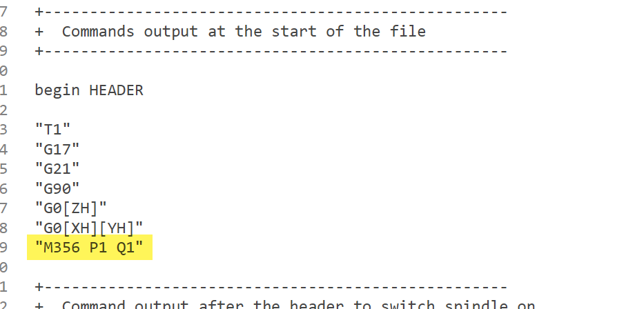
Using the instructions from the Manual Control section of the Technical manual, I was able to force my LEDs to always remain white by executing the M356 P1 Q1 command. You could add that to the Program Start event in gSender but I ended up just adding it to my VCarve PostProcessor (because that’s what I thought of first) as follows so that the command is inserted at the start of every job’s GCode:
Assembly Tip:
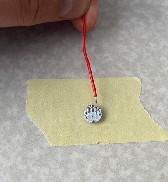
I was finding it quite a challenge to solder the wires to the pads on the back of the LED because the LEDs were so small and lightweight. I ended up using double-sided tape to stick them down to my counter.
I then tinned the wire and the LED’s pads. That eliminated the need to add any solder when applying the heat. I would just press the soldering iron down on the wire and it would sink into the solder that was already on the pad:
Parts List:
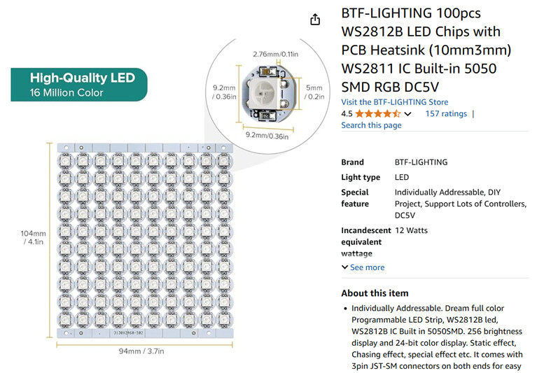
LEDs: WS2812B 5050 SMD RGB DC5V
https://www.amazon.ca/dp/B01DC0J0WS?ref=ppx_yo2ov_dt_b_fed_asin_title
I’m not sure what happened to the price but when I ordered them from Amazon they were $26.87 CAD for a pack of 100. Now they are $64.23 (yikes).
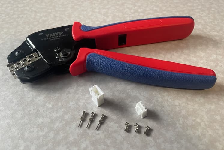
Connectors:
The male 3pin JST-XH connectors and clamp came from Amazon. I don’t recall where I ordered the female connector (for the cable back to the SLB) but I know it wasn’t Amazon. All the Female ones on Amazon were the ones intended to be soldered onto a PCB:
https://www.amazon.ca/dp/B0C6DKZC4K?ref=ppx_yo2ov_dt_b_fed_asin_title&th=1
Spindle Ring Light.stl (456.6 KB)