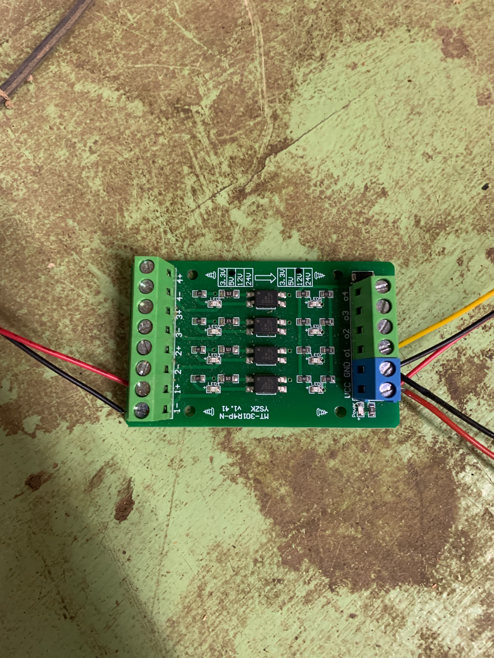
I’ve not gotten a Longmill yet, but plan to. I currently have a Shapeoko 3XL and a Sculpfun S10 laser module attached to it. It works quite well when plugged in to the PWM port on the Carbide 3D control board. Unfortunately, the control board only puts out 5V PWM max and the Sculpfun module can take up to 12V. The Longmill also puts out 5V PWM, so I’m going to have the same issue on that machine. Someone recommended that I get a logic board that would convert the 5V PWM to 12V. I have tried that, but it doesn’t work as I’m expecting. The laser stays on all the time and is not PWM controlled at all, from what I can tell. The image shows the board that I put between the PWM output from the CNC control board and the laser.
This is how I wired it:
1- PWM GND from control board
1+ PWM positive from control board
VCC: 12V+ from laser power supply, 12V+ to laser
GND: GND from laser power supply, GND to laser
o1: PWM signal to laser
Is the Laser expecting a signal referenced to GND on the control board? Opto-isolators (the 4 chips across the centre of your PCB) isolate signal and ground. Linking the Black wires would re-connect the GND levels - but you need to be sure it won’t harm anything before you do so.
Signal frequency of the PWM signal. These Opto-isolators should be good for 40KHz or better, limited by their 100uS output rise-time. What is not clear on their data sheet is what the input signal limit frequency is, but it is reasonable to assume it is the same. The PWM output from the Arduino board (presuming that is what you have, ShapeOKO controller is essentially an Arduino) should be much slower than this so should be handled OK.
Current draw on the PCB input is overwhelming the controller PCB’s output current capability. I recall that Arduino processor output pins are limited to a maximum of 20mA per pin, which if exceeded could result in the pin going into self-protect state (probably to zero volts). Placing additional resistance in the red 1+ line would prove or disprove this - what is there (if I have read it right) is 270 ohms, so I would try adding 270 or 330 ohms if you have access to any leaded resistors.
The signal is inverted through the action of the opto-isolators, so 10% PWM is being ‘seen’ by the laser controller as 90%. I believe some laser controllers have the ability to invert the PWM input, and I think there is a GRBL setting to do the same in the $$ parameters.
What to try? I would look at signal inverted first, extra 1+ side resistance second, then GND linking.
All a bit of guesswork…
Caveat Emptor - I am familiar with electronics and what makes the ‘magic smoke’ leak out, but if it is not your thing, please go carefully interpreting what I have said
@SirGawain ,
Why do you want to increase the voltage? It won’t increase the power output of the laser. The power output is determined by the pulse widths (PWM = Pulse Width Modulation) of the PWM signal, not the voltage level.
Just curious.
What you say that the laser stays on all the time, can we assume that you have set $32=1?
Also, I’m confused by two of your statements. You say that “it works quite well when plugged into the PWM port”. Then you say that "the laser stays on all the time and is not PWM controlled’. With respect, I find those two statements to be contradictory. Maybe you can set me straight?
I guess that should have been the first question that I asked. I’ve got only a basic understanding of PWM. So when the signal is at 100% coming from the control board (which I assume means it is outputting 5V), the laser is seeing that as a 100% signal?
So you are saying that the output voltage from the CNC control board doesn’t matter to the laser, it’s only the pulse width.
So my assumption has been that increasing the output voltage (to it’s 12v limit) would increase the laser optical output. I’m not able to measure the actual optical wattage, but I’ve not been getting the results out of the laser (as far as cutting depth) that I expected. I guess I’ve made some assumptions based on faulty understanding of PWM.
To summarize: I can get a Longmill MK2, which has a 5V PWM signal and a 12 or 24 v PWM input laser and still expect to get 100% power out of it. Is that correct?
Yes, that was confusing. When I have the laser connected directly to the PWM output WITHOUT the logic board it works fine, but with less power than I’m EXPECTING. I don’t know how much it’s putting out, since I can’t actually measure the optical wattage. I just am not getting the cutting results that I was expecting from it.
When I connect this logic board between the CNC control board and the laser is when I’m getting the problem of the laser staying on all the time and not seemingly being controlled by the PWM.
I think your summary is correct. In your first post you said that the Sculpfun module “can take up to 12V.” I’m assuming that this means that it will also work with a 5V input. That being the case, you should get full optical laser power without having to increase the +5V PWM signal. If you search the Sienci Forum for me and laser stuff you will find a write up on how the PWM works.
@SirGawain In LB, some recommend that you set Smax to 255. The LB developer recommends 1000. I set to 1000, as it is easier to set percentages. Then, make sure that $30 is set to the same value. The key is not whether you use 255 or 1000. The key is that Smax and $30 are the same. If they are different, you will not get the power results you are expecting.
It’s would be a good idea, also, to follow @paullarson advice to read his laser explanation on how PWM works. With that information and a volt meter, you can easily ensure that the PWM output from the controller is correct.
Thanks guys! I have confirmed that the Smax and $30 are both set to 1000. I’ll read your PWM summary, @paullarson and see what else I can discover.
I’m glad to know that I don’t need to find a Laser that is only a 5w unit! I really would like to get one of the newer 20 or 30 watt optical output modules. They are all in the 12-24v range on their PWM input. But, from what I’m hearing from you, a 5V output from the control board will still drive it to 100% anyway.
I’m curious, if that is the case, why do they list the voltage at all? If it just needs a PWM input regardless of voltage, why the rating?
@SirGawain Well, Gavin, that’s the only things that I can think of. I’m assuming that you have properly focused the laser and that your power and feed rate settings are appropriate. There are excellent files on the LAHobbyGuy’s site to test both of those factors.
However, I would like to back up a bit. You have said that you are not getting the cutting depth that you expected. What is it that you are expecting? A 5w laser really is only good for etching. I have a true 10w without air assist. It will cut 3mm plywood after too many passes. Many here complain that the Sienci 7w laser will not cut 1/4" material. Yup. IMHO, if you want a laser to cut, get a CO2 laser. That’s an overstatement, I admit, especially since there are now 30 and I think 40w diode lasers. However, the vast majority of low power diode lasers are not appropriate for cutting, regardless of some of the ridiculous claims. Again take a look at the LAHobbyGuy. He does excellent reviews of lasers.
@SirGawain ,
I tried to look up the specs for the Sculpfun S10 laser module and what I could find was pretty scant. I think by definition PWM signals are less than 5V. I’ve also seen the signal called PWM/TTL. TTL is old engineerese for transistor transistor logic which was, originally, 0 to 5V. As transistors have become smaller the voltage has come down, too. So, I’m thinking, that the 12V listed in the Sulpfun documentation is the max voltage to use to power the laser module. I don’t think they ever intended you to drive the PWM input to 12V.