Even if the Y rails are mounted perfectly, the gantry may become out of square due to movements which exceeded the motors force (or hitting an obstruction). It is desirable to easily regain the squareness without the addition of sensors/switches and wiring.
After mounting the Y rails, the gantry was moved until it hit the “Y” rail supports at the front. The gantry was actually moved very close to hitting the brackets and then the lead screws were turned manually until the gantry was pinned against the front supports (you can also use the “precise” setting and slowly jog the gantry until neither Y screw show additional movement). G sender may show increasing increments on the monitor because the system is “open loop” and it does not recognize the non movement.
The first step (after hitting the front Y supports) was to make a test cut from that position. The longmill was jogged 24” in each direction to route two edges of a piece 24” x 24” x 1/4” material. The resulting cuts were checked with a verified accurate framing square. It was noticed that the two machined edges were not square. The edges (in my case) were obtuse (greater than 90°) and that meant the right Y rail needed to mechanically stop earlier. If the measured angle was acute (less than 90°, then the left Y rail needs to mechanically stop earlier.
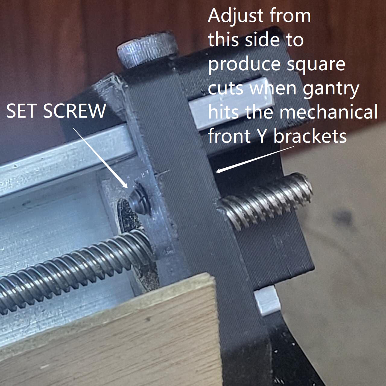
A hole was drilled and tapped (10/32 thread) in the front right Y rail support at a position that will hit the gantry side plate since the measured angle of the test cuts revealed an angle of more than 90°.(if the test cut angle was less than 90°, then the left front black Y support would need to be drilled and tapped) A set screw was inserted and adjusted stop the Y rail (see attached picture) Test cuts were repeated and checked with the framing square until the adjustment of the set screw resulted in cuts that were perfect 90°.
After bringing the Y to the now aligned and “squared” stops, the X axis was moved until it mechanically hit the Y gantry bracket (left side). The mechanical stops now became the ZERO positions for both the X and the Y axis and were zeroed on G sender. After that, 2 small 1/2” x 1/2” x 24” wood strips were fastened to the“spoilboard” about 1/16” beyond the “zero” line so they can be machined while in place. After zeroing against the mechanical stops (and the g sender values were set to zero) the long mill was jogged to get both X and Y positions to .125”. A .250” router bit (.125 radius) was inserted into the collet to machine the fences so the resulting fences will now represent 0,0 when the X and Y hit their mechanical stops.
When the Longmill is initially powered (or if something happens mid-project) I am able to get X and Y axis back to their perfect position. Just move the X and Y until axis until they hit the mechanical stops and then ZERO those two axis on Gsender. ( Z would require a different method to regain its original position, discussed later)
While having the zero postion for X and Y at the mechanical limit of the machine will maximum workpiece capacity, it may be impractical if machining the edge of the workpiece is desired. To move the workpiece away from the mechanical limit of the machine, you just clamp the workpiece to the spoilboard with strips of materials, of known dimensions, to offset the workpiece from the fences. Then jog the X and Y positions to positions that represents the dimensions of those strips. EXAMPLE : If you put a 1” strip of material against the X and Y spoilboard fences to space the workpiece off the fences before clamping, you would jog both the X and Y axis to 1” and then ZERO those two axis on G sender. This will reestablish the reference for the new position of the clamped workpiece (assuming that the lower left corner is the origin of the project). If the machined is powered down or there is a computer glitch or mechanism stall, just jog the machine to the X and Y mechanical stops to ZERO it, then jog those axis to 1” (if a 1”strip was used to offset the workpiece) and then ZERO it again. You are now all synced again!
If Z axis position is desired to be reestablished after a power glitch, mechanism stall, etc, then follow this procedure when the project is started : After installing the cutting tool in the collet, jog the Z axis to its maximum position (hits the mechanical Z limit). Now zero G sender on the Z axis and lower the cutter until it touches the top (or the bottom) of the workpiece (based on how it was referenced in the toolpath software). Note the distance that G sender now reports on the Z axis (write it down!). Now zero the Z axis and proceed with your project. If a power glitch, mechanism stall, etc requires the Z position to be reestablished, then raise the Z axis until it hits the mechanical limits, zero the Z axis on Gsender and then jog the Z axis to the position that was written down and then zero Gsender again. You will now be able to recover the positions of your machine under any condition and hopefully complete the project with the best results!
Perhaps this procedure was already discussed in the community and I apologize if I am repeating it.