I have a problem with my banggood laser that everyone has been getting. I can get it to turn on, the button on the driver board reduces the laser power. So The hardware appears to be working correctly. The problem I am having is with the spinpwm port on the longmill controller adjusting the power. I get 100%power no matter whatever command I send in either lightburn or UGS. I have sent the setup commands ($30=100, $31=0, $32=1) to enable laser mode and set power range.
I can burn a project using light to control the laser position but not the power and the same with using UGS and gcode. The gcode clearly adjust the power but I am not seeing that on the laser side. I am getting 2.5V at pwm/ttl pins on the driver board and at the spinpwm on the longmill controller no matter what commands I send. I’m not sure what else to do? Any suggestions. Andy from Sienci suggested I look for answers here. Any help would be aprreciated.
Did you make use of the instructions i put in the following posts to measure the SPINPWM output with a digital voltmeter? You can measure with the laser unattached. If you see similar results the LM controller is OK. The second post shows commands you can use to control the laser and run the tests right from the UGS command line.
I had to replace the Arduino board to correct my issues with the laser doing the same thing. Just ensure you replace with a quality board as I had a few cheap ones and they had the same problem.
I checked the spinpwm port with out the laser connected and got approximately zero volts when sending either M4 s0 or M4 s100. I had about .028 volts the entire time when sending either code after I enlabed the laser mode and set my $31=0 and $30=100 and $32=1. So I am getting no response from that port it seems. If I connect the laser and power it on I get a constant 2.5V at the plug no matter what command I send for power and I have 2.5V at the pwm/ttl plug on the laser driver. Any other ideas?
Thanks for the info. I have a feeling that is what has happened. The signal is being sent from both UGS and lightburn but nothing is happening at the port end. It seems to me that there is a break in that circuit. Thanks for the info. I’ll see if there is any other thought on things to check before doing this. Was it important to flash the board before installing it on to the longmill control board or was this just the order you took to install it?
Sounds like a bad controller (maybe arduino as @Kyfe suggests). It maybe going up to 2.5V after you plug the laser in because of pull up resistors on the laser board. If this is a new unit Sienci should replace the controller.
One more thing, @drounds67. I just noticed that you you only tried S0 and S100. Both settings would result in a DC voltage. If you were measuring with the voltmeter set to AC this is what you would expect. Try measuring again with an S50. With this, if you are set to AC you should still get a different voltage. Alternatively measure with a DC setting. Of course, if your previous measurements were DC measurement you can ignore this post.
So this is exactly what I was seeing on my setup. Same laser as the video. Without the laser hooked up, the SPINPWM tested (per your posted info regarding check of the voltages) showed it worked fine till the laser was connected. At that point the laser was pulling that the Arduino signal to 2.5V+ with no Sx control which resulted in the laser constantly being fired regardless of my Sx value with an M4 command. My solution was touched on in a single message in one of these laser threads (I went through them all) which was to add a 1kohm pull down resistor on the PWM+ signal coming off the laser control board. Once I did that, the Arduino was able to sweep the voltages (0-5V) with the laser connected.
Also something during the testing for voltage during debug on the SPINSWM signal was to not set the $32 to laser mode ($32=1) during this check since it would require x/y movement in order for voltage to be seen. I must have missed that in the thread which had me thinking the Arduino was bad for a few minutes. Obviously, set it to laser mode when you’re ready to use.
Anyways…for what it’s worth. I know most on here have not needed to add that pull down resistor, but it was the only way I could get the laser to work on my end. Thanks for your work to document your efforts as it was very helpful!
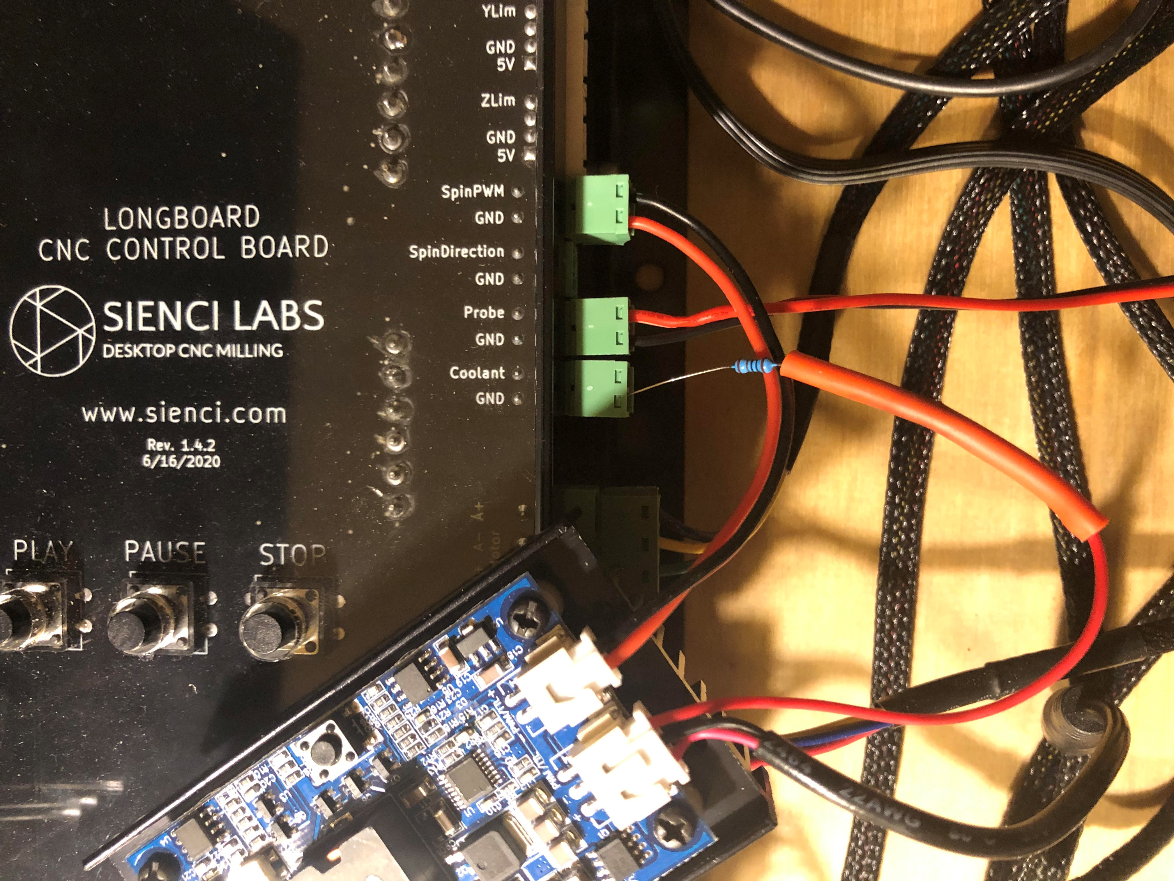
@smpico1 seem to be having the same issue. This fix you mention is a bit beyond my pay grade. If possible would you be able to post a picture of the installed resistor for me?
The GND I used to connect the 1kohm resister was based on convenience due to wire length. It just needs to be grounded so any will do.
The laser kit did not come with the 2 pin connector that would go from the controller board of the laser to the SpinPWM and GND connections on the Longmill control board. You’ll notice the red and black wires appear to go into the wrong connection but it’s actually the connector wiring that is backwards. It was all I had that would fit into that connector.
The single red wire coming out of the 3 pin connector on the laser controller and the PWM+ signal on the 2 pin connector are actually connected together on the board. I decided just to use that single red wire from the 3 pin connector to add the 1kohm resistor and tie it to GND.
Once connected this way, for me, when plugging in the laser, it will not immediately fire at full power. It will just turn on the RED led. Once you hit the button on the laser controller, the laser will turn on (Green LED) but at low power (for alignment). Once you actually start a print with whatever software you plan to use (I use Lightburn), the laser will fire based on the power settings you’ve entered into Lightburn (or other program).
Hope this is of some help. Let me know if you need more info and let us all know if you’re able to get things working on your end.
@smpico1 I received the resistors today and installed following your picture/instruction and IT’S ALIVE!!! It works! Thank you for all your help. It was bound for the garbage bin without it!!