I have been controlling my DIY longmill with an Arduino and a CNC shield V3 with DRV8825 stepper drivers. That seemed to work fine up until today, when it decided to release the dreaded magic smoke.
I was thinking that I should upgrade to the beefier TB6600 drivers used on the longboard. And if I’m going to do that, maybe I should just build a DIY longboard (the Gerbers were shared by Sienci, and I have fabbed PCBs before). That brings me to three questions:
- Has anyone built their own longboard controller yet?
- Are there any errata that I should be aware of?
- Does anyone know where to get the TB6600 drivers used on the longboard? There are loads of TB6600’s on AliExpress, but they all have screw terminals soldered to them. It looks like the ones Sienci uses have pin headers instead, which in turn get soldered to the longboard PCB.
2 Likes
Hey Corey, that sounds fun! No one else has made their own LongBoard controller that I know of yet but I’d certainly encourage you to give it a try - sounds like you know what you’re doing 
One thing I’d mention is that we just finished the 4th major revision of the board which has some added stability on the I/O and the ability to control via an external switch or E-stop. If you want the most recent design, I’ll let you know as soon as we have all the new files posted: should be in a week or two once we complete all the verification (it’s been ongoing the last two months).
As far as drivers are concerned, we find a manufacturer that deals with them and make a special order to have pin headers take the place of the terminal headers. How are your desoldering skills 
1 Like
Thanks for the additional info – it’s very much appreciated.
I’d love to see the latest revision of the LongBoard when you are ready to share it.
I’m curious to know what issues you were seeing with regard to the I/O stability (enough so that you decided to spin a new revision to fix them). It looks like the drivers are controlled directly by the output pins on an Arduino. I’m not sure how you can improve the stability in that case? Unless, perhaps, the drivers need a lot of current to their control inputs (pulse, direction, enable) in order to operate. In that case maybe you’d use the Arduino to switch on/off a current source…?
Right now I’m trying to decide between a few options for my controller:
-
Make an exact copy of the LongBoard PCB, and desolder the TB6600 screw terminals. I can desolder when I need to, and I have a hot air station too, but it’s probably my least favourite part about tinkering with electronics
-
Modify the design to use a smaller PCB footprint (== cheaper PCB). I could use the existing molex connectors on the TB6600 boards for the control inputs, plus some external wiring for the motors. I was thinking about stacking the drivers perpendicular to the PCB to make a ShortBoard, if you will 
2 Likes
Hey hey hey!! Looking snazzy in the white @frankchannel 
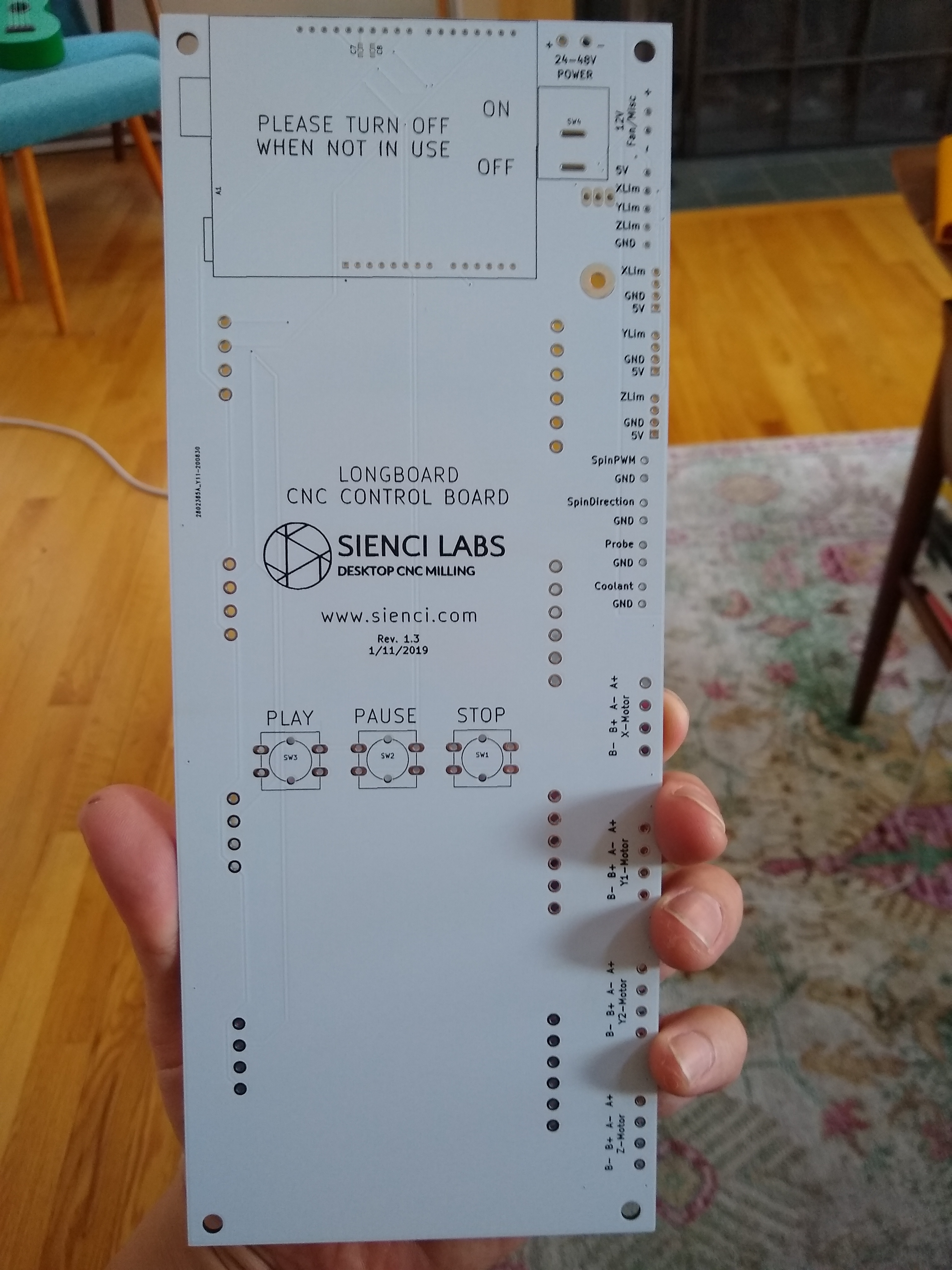
So I’ve just soldered up my DIY board, with one motor driver (I figured I’d test it with one motor before “committing” to solder the rest). Unfortunately it’s not working, so I’m in debug mode.
When checking voltages I noticed that the drivers are not getting +5V from the Arduino. This seems to be because there are 2 different grounds on the board: “GND” and “GNDA”, which aren’t tied together. The drivers are connected to “GND” whereas the Arduino is connected to “GNDA”. This leaves the +5V signal on the driver floating. It seems like these two grounds should be tied together somewhere?
Any thoughts?
1 Like
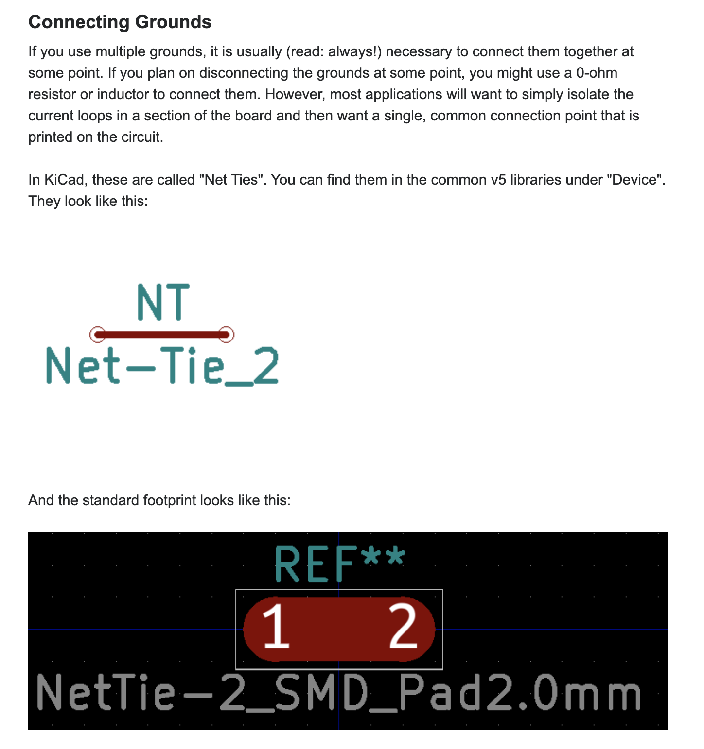
According to this stackexchange post analog and digital grounds should be connected at one point in the board/schematic:
However, I don’t see any connections like that in the schematic/pcb layout. I checked with a multimeter, and the analog and digital grounds on my DIY pcb (made from Sienci’s design files), are definitely not connected.
1 Like
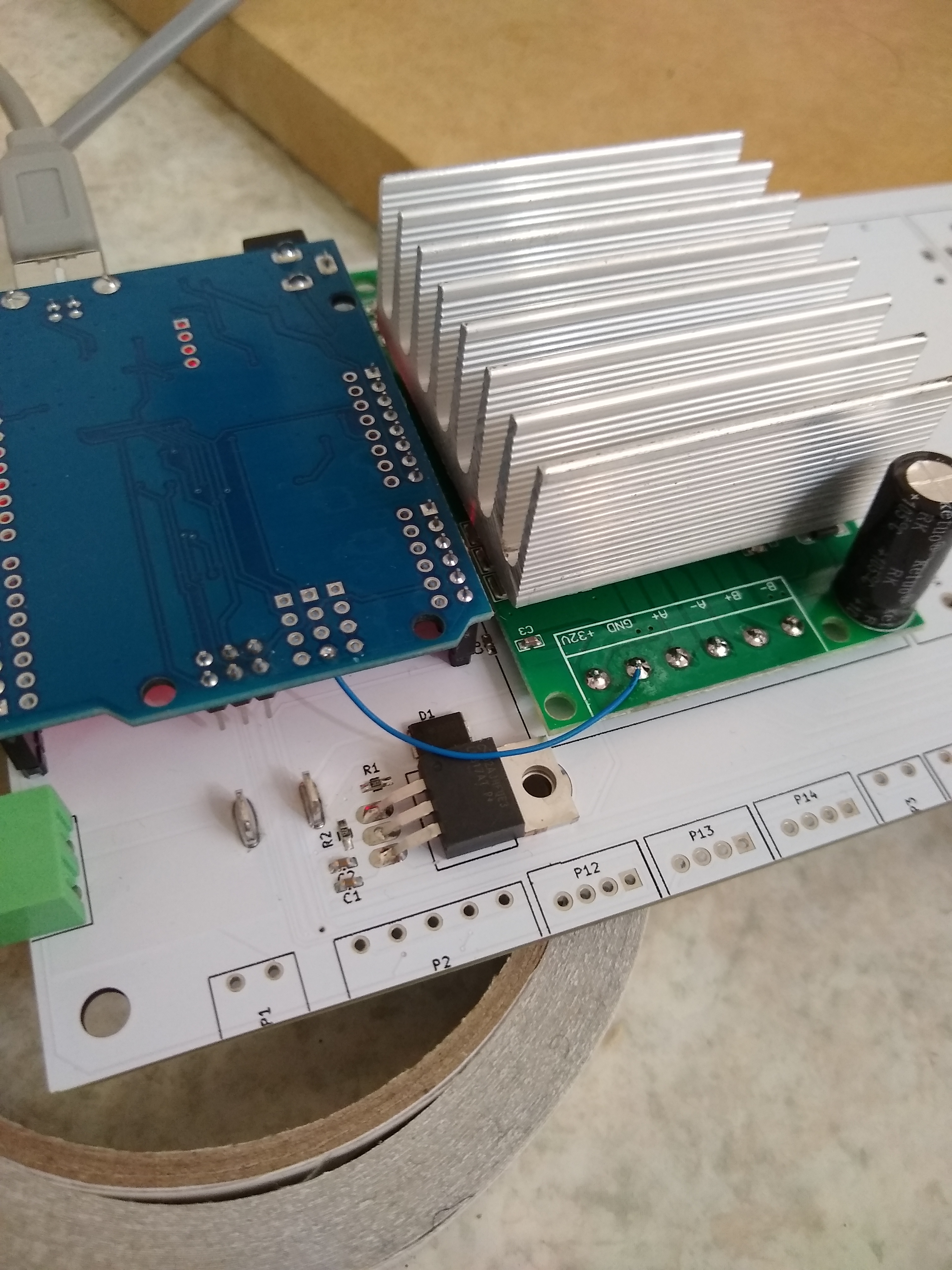
Investigating the above problem I went ahead and added some point-to-point wiring between the analog and digital grounds:
After making that change it works!
My big question now is why did this happen, and are the v1.3 longboards different from mine (i.e., do they have GND and AGND tied together?). If so maybe a correction should be made to the posted design files…
1 Like