On the Shopbot PRS-Alpha at our local maker space I wanted to improve the time estimations for designs and CAM done in Fusion 360. I took about 6-8 jobs and noted what the original fusion time was and I carefully logged the actual machine time and then came up with a machine time factor of about .53. That gets me within probably 10-12% or better accuracy in the time estimator in the Fusion 360 simulator for the ShopBot.
Has anyone done any comparisons of estimated versus actual for the Longmill when running GCode from Fusion 360? It would be really good to get our arms around the appropriate time factor to improve time estimations.
Jeff is asking if anyone has compared estimated time vs actual for the Longmill when utilizing Fusion 360.
I never thought of doing this but it would make sense. I guess I do it in my head at work with the 3D printers. Working out a actual x factor would be even better.
Correct. CAM software doesn’t know anything about your actual machine. It can do it’s best to estimate things based on the inputed rapids and feeds/speed but there are a lot of other variables that affect performance. As well, how the machine ramps up and down when you are doing advanced things like smoothing and slowing down for corners etc. that Fusion 360 allows are unknown to the software. This is why the factor exists in the first place. Likewise, I suspect GCode complexity and the horsepower and efficiency of your gcode sender may play a small role as well. There are a lot of moving parts in the design/CAM/sending/cutting path.
To my surprise, when many people realize that the difference between the time estimate and actual time is significant they just assume “it doesn’t work” and choose to ignore it. The internet is full of these comments. I can happily report that with a few days of carefully tracking performance on the ShopBot, I achieved that very usable window of accurate within around 10% +/- of the estimate. Sometimes it estimates high and other times low. I’ve not been able to ascertain what the differences might be, but it’s close enough for my planning needs that I haven’t pushed it much further.
I did try one time to fine tune it, but I found tuning the factor further made certain jobs more accurate while making others less accurate. I dialed back to a setting that gave me relative consistency and I’m pretty happy with it. Now we just need to find it for the Longmill. As I sometimes had to remind my German co-workers “we’re looking for accurate, not necessarily precise”.
By observation, I believe the factor is expressed in something like “1.0 is if your machine performs exactly like Fusion 360 models expect and .53 (roughly what I use for the Shopbot) means your machine is 47% slower than expected (aka it performs at 53% of the 1.0 baseline)”. Likewise, a number above 1.0 would indicate it can perform faster than the default model “machine”.
To get my samples, I noted the estimated times for a number of toolpaths from large jobs in the simulator (with a default machine factor of 1.0) and then carefully tracked actual times with a pencil and paper, recording the total toolpath job time at the end of each toolpath as noted in the gcode sender/control interface. With a bit of division, eye balling and averaging was able to come up with the .5ish factor - then I repeated the process with some new jobs and dialed in to the .53 I’m pretty happy with.
I should mention I decided to set up each toolpath as an individual job so I had clear start and stop points and time to record my data. I also named each toolpath with the tool in question like “14 Comp Contour” for 1/4" compression bit contours or “8mm drill holes” for a drilling operations. Some of the overall projects had 2-4 tool changes, so this helped me capture what tool was used for a given operation as well. I didn’t use the tool data in the end but if we capture it here we may be able to filter and tease out some additional details allowing those who primarily use certain bits to further fine-tune their factor.
Of course, I was a sample of one. With the much larger community here, if people post their CAM package, the time estimate and the actual observed time we should be able to get a decent sample set and hopefully dial in a good number for the Longmill.
This will also be useful for comparing the stock design/build with DIY versions that may use similar but different components, as well as looking at any benefit of upgrading to the larger motors that are a bolt-on option, should someone explore that. Youtube is full of people who have “upgraded” their Shapeokos etc but there isn’t always a clear indication of the measured benefit or the cost/benefit when watching their updates. We can do better.
Hey @andy or @chrismakesstuff, maybe someone on staff could whip up a quick page for the community to capture and database of estimated vs actual details as self-reported by end users? Then you could provide a rolling estimate overall or even allow filtering for a given bit size or material type? I’m unsure how much bit and material matter to the modeling in F360 but easy enough to do to experiment with.
Off the top of my head I’d recommend (d) for default value in form:
Longmill Config: Stock (d) || Modified
Config Modified: Text field, if applicable, please describe modifications briefly
Router: RT701C (d) || Dewalt xxx || Ridgid xxx || Bosch xxx || Others added they emerge
Collet: .25" (d) || .125" || 8mm
Bit: 2 Flute Downcut (d) || 2 Flute Upcut || 2 Flute Compression || 60 V-Bit || etc. etc.
CAM: Fusion 360 (d) || Estlcam || VCarve Pro || (I don’t know which ones offer time estimates and factors)
Job Type: Contour (d) || 2D Pocket || 3D Pocket || Drilling || etc. || Other
Estimated Toolpath/Job time (seconds):
G-Code Sender & Platform: UGS PC (d) || UGS Mac || UGS Pi || ??
Actual Toolpath/Job time (seconds):
Thoughts?
-Jeff
PS - For those hoping to use the Longmill in a commercial application or where time/access to the machine is limited, having accurate estimates is critical. Having an accurate machine time factor would go a long way to making the machine more appealing to a broader and more commercially minded audience as well as for busy Makers.
That’s an interesting idea Jeff. In the past if I’ve noticed that the estimated time generated by a certain program is way off the actual time then I just don’t bother paying attention to it and instead use a program which has a more reliable job estimation time, but I’ve never thought to create a ‘machine time factor’.
I’m not exactly familiar with the approach taken to estimate cutting times, but it seems that if the software knew exactly what the machine default speeds, acceleration settings, etc. were then it should be able to theoretically predict the cutting time exactly. I suppose each program must assume a default machine configuration, and ultimately this is what affects their cutting time estimates?
I know that some people here would likely be interested in getting a more accurate cutting time estimate on their jobs, so I like your recommendation to start a user filled form; just need to decide where / how to best host it so that it can be easily accessible. Suggestions?
I’d suggest a standard “project” that we could all produce and record
our results (Benchy type deal). Then have a thread where we can post,
tally and compare.
Greg, I know you’re a good guy and you mean well so please consider this good spirited feedback. We all appreciate the direct experiences and details you’ve shared about your Longmill journey. However I did want to address your recent comment in this thread:
I hope you have never had a fire or required the services of first responders. Even if you haven’t, I suspect you still appreciate the existence of the fire department.
Likewise I hope you’ve never needed a crumple zone or an airbag, but I think we can all agree that they improve the overall risk/benefit of driving a vehicle. Things don’t have to be directly applicable to one individual unique situation to be relevant to a broader community like the one Sienci is building around the Longmill. It takes a village to raise a product.
A general Internet forum rule of thumb is: If a topic isn’t applicable to you or you can’t add value, it’s more helpful to stay silent. If someone is way off base, they will get silence from everyone and the topic will fade away in to the archives. Conversely, everyone is typically welcome to join the discussion when they have value to add or for the occasional witty retort or social banter that adds a bit of personality to a community.
It isn’t particularly helpful to say “I don’t need that, so why bother?”. The silence covers that. Also, saying that can be construed as diminishing the contributions of others, some of which will prove to be highly relevant to many people in the community, even if this particular item doesn’t fit your needs.
At best, a phrasing of “That’s interesting, I’m not sure I’d have a use for it, but help me understand why you would want that. Maybe there is another way to solve the problem?” would be better received and indicates (what I believe to be) your desire to be helpful.
Nonethless, to help illustrate the relevance of the topic, I’ll share a few examples with you that will almost definitely apply to some of the current and likely future Longmill buyers. We all benefit when the community (and Sienci Labs) continues to grow. I’m all for a big tent, but even without it, here are some examples:
Acoustic limitations / Noise By-laws
Home (and some small business) CNC users may have (as I do) municipal noise bylaws that are fairly limiting and aggressively enforced. Folks in my situation can only be cutting during certain hours of the day and certain days of the week. They may even be limited in how long they can create a certain level of noise. So having an accurate time estimate is critical to planning when you can cut which toolpaths, which may require multiple stops and starts over multiple days to finish a whole job. This allows you to organize the tool paths to fit the restrictions.
Space Limitations
Not everyone has the luxury of a full time shop. Many of us (me included) have taken over all or part of the family garage to create a work space. At times that space is required for other family (and automotive) purposes. The beauty of the Longmill being a manageable size and somewhat mobile allows for creative mounting and even (vertical) operation options. However, operation in any orientation will likely cause noise, space and dust/safety conditions that block other family activities in the garage. If you can’t accurately predict the cut times and play nicely with others users of the space then the SAF (spouse acceptance factor) trends towards zero and friction occurs.
Job Scheduling
For anyone doing work that they hope to be paid for, it’s always the trinity of time, cost and quality (pick any two).
Once you build a backlog of business, it is critical to know approximately how long the machine will be engaged on a given job so you can accurately estimate how soon you can do the subsequent job. If I have jobs A, B and C committed and roughly scheduled and then someone requires a rush for job D (or to move up A, B or C) - I can determine if I can accept the job by considering the impact on the other clients and the committed timelines. Without this, I am blind. For something a little closer to home, @chrismakesstuff would never have been able to consistently deliver the tally of machines shipped (and keep the hungry hoardes at bay) if he didn’t have an excellent handle on inventory levels, sub-system build and assembly times and final packaging times.
This is a fairly common business issue in many fields, but given that the CNC is a big computer, which is a big calculator that uses known quantities to perform it’s duties, we should be able to feed it the right inputs to allow it to accurately estimate. We just need to collect enough data to get us in to the right general zone… which brings us back to the original purpose of this thread, to start that discussion.
Cost / Opportunity Cost
Whether home users, semi-commercial or commercial users we all run in to cost & opportunity cost analysis. Any job is only worth a given amount of time and effort and beyond that you may discard it or choose to address the requirement in a different fashion (or not at all). As I often say “I’d like to do X but it’s not a $500 problem”.
You can’t make an informed decision about options if you don’t have a rough order of magnitude of the time/cost invovled (and by extension the opportunity cost of what else the machine could be doing or what else you could be doing with the time and money the job would consume). As an example, I suspect a number of users here have access to other (often larger/faster) CNC options at work or at a maker space, but those have different capabilities, costs and time/access quantum associated with them. I need to know what the Longmill option will consume in time so I can compare. It won’t be everything to everyone on every job.
CAM Operation Selection & Trade-offs
There are often multiple roads that lead to Rome. Many desired outcomes could be achieved in more than one way, for example a drill or bore or even pocket operations for bench dog holes. Depending on the level of detail and finish passes and acceptable cost for the given job, one is preferable to the others. When doing the CAM programming it is helpful to be able to compare two adjacent roads that both contain some trade-offs against their respective operation times (and everything tied to those operations times, as noted above). Fusion 360 is great for integrating all this in one spot in the simulator so you can compare and contrast options while “proof reading” the programming.
I’m sure others could chime in with examples of why they would appreciate or even require relatively accurate time estimates. While I appreciate that you have the apparent luxury of relatively unlimited time, space and finances that make machine time estimation of little interest - most of us are not yet so fortunate and would appreciate accurate times.
Finally, the overall market appeal of the Longmill and it’s potential to appeal to as broad a potential customer base as possible suggests this is important. Many objections stopping people from buying can be addressed directly or indirectly when an operator can accurately predict machine time. So, there is that…
I’m not personally familiar with Benchy (will take a look) but I am a big fan of using some off-the-shelf free service for this if there isn’t someone at Sienci who can spare the cycles to toss it together. Even a Google spreadsheet might be viable, although I’m not sure how you would stop people accidentally trampling on the data already stored in it. I’m sure it can be done though.
Since the goal is to compare estimated/actual time, the specific material or operation isn’t even that important once we have enough samples. The outlier materials and operations will become apparent and we should be able to find the center of the likely bell curve that we’re looking for.
I’m a long way from first year statistics and I couldn’t understand my Norwegian professor very well anyway, but I’m sure one of the engineering/CS experts hiding around here can steer us in the right direction for platform and statistical approach.
Appreciate your comments above. Exactly how I was feeling but unable to communicate nicely.
As to Benchy, it’s a item that is 3D printed to test a 3D printers capabilities and accuracy. You use fixed settings to print the object, once done you measure and compare results. This can be used on multiple machines as a benchmark for comparing printers.
I was just thinking for us to use something similar so our results can be compared
but I understand from your post that no matter what project is done we should be
able to see a pattern eventually.
A shareable google doc with simple password might be the way to go for data collection.
Hopefully my machine ships this week and I’ll be able to play along with the big kids.
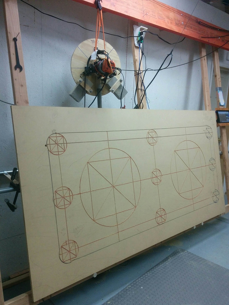
This is quite interesting, albeit different but parallel to what I was saying. Separate from the machine factor to help with estimating, I think what you’re talking about could be really good to help with calibration and trouble shooting. Maybe something like a known, exactly sized reference design that prints a circle inside a square in each of the four corners of the workpiece, as well as in the middle. Or perhaps a different shape is more appropriate, but the circle and square would help show line straightness, right angle-ness, and ability to handle curves. And cut text for X and Y axes so you know which side is “up” when measuring later with your caliper… Maybe throw some text and parallel lines of reference distances in there too.
I’m thinking publish it with a nice PDF of the expected dimensions using a particular bit like a 1/4" downcut and it can be used to validate machine performance in the event of odd issues cropping up. @Lumpy is that where you are headed?
And as an aside, Sienci could publish the expected job time at stated feed and speed rates and you can also compare your actual time to the expected time to potentially identify if something is off?
I have been following the Maslow CNC project for a long time and this is an area they haven’t yet been able to get their arms around because it always comes back to “no two machines are exactly the same” - which is not a problem with a stock Longmill. It should basically be the same at a given size.
Now that I think about it, I really like this idea. Reference design in GCode with well documented dimensions and cut times, target bit type and material. Make it one of your first cuts to confirm machine is properly configured and calibrated. Write the date and time on it and store it away as a “birth certificate”. Then, in the future, if you think things are worn or the machine has “gone out” in some way, re-run the reference case and compare the results.
I have a feeling that doing this across most or all of the user base would allow some signatures to emerge that could then be quickly identified. “Hey, my machine started acting up and ruined a couple of jobs. Nothing obvious wrong but now when I run the reference cut it looks like X (picture) and three of the corners are correct but the lower right corner and center and out of square and out of round. Any ideas?” And because everyone is comparing to the same reference we’ll be able to say “Yes, that looks like your whosawhatsit is loose or worn, try this…”
Thoughts? @chrismakesstuff and @andy I’m more of an idea guy than a hard core engineer. I have a feeling your backgrounds are bubbling over with what the right design would contain to be useful in this scenario.
@jwoody18 That is exactly what the Benchy model is about. Using fixed settings with a fixed dimensional design. It would translate well into the CNC world.
I like the way you think! Your comment triggered another idea for the reference design - multiple depth slots adjacent to each other in each corner and in the center say at 1/8" intervals to 5/8" in a 3/4" piece of MDF (perhaps an off cut from the piece used for the bed during the build?). And for those of us trying hard to work in metric, perhaps the reference comes in imperial or metric options.
[EDIT] Following along the depth idea, I can see how having those identical clusters of reference slots in the five positions on the reference piece could be quite helpful in illustrating potential issues caused by an uneven bed (or unbalanced clamping of the workpiece).
Since one of the key benefits of CNC work is the consistency/accuracy/repeatability of the machine, I think this approach could also help the brand side by illustrating how good the machine is. It also occurs to me that it would provide a nice comparison for someone testing longer term vertical milling and it’s effect on machine life and accurracy etc. Having a community wide reference test design would also allow for feed/speed benchmarking and give a good comparison to someone who might upgrade to the 76mm motors, just sayin’.
About half way down the thread he posts the files in various formats (keep scrolling, he updating them a bit past the first time her posted them). But this is the kind of thing I was thinking could be adapted for the Longmill. I’m afraid mine is still in the box as an unrelated electronics project has consumed what project time I have and that’s only half done. Hopefully I’ll get it and the car it’s going in to out of the garage soon and get my Longmill assembled!
JWoody: I have no idea what this pattern is for, but I was intrigued, so I downloaded the .dwg Maslow file. It was full of open vectors, so VCarvePro wouldn’t cut it. I redid it in VCarvePro as near as I could. I down scaled it, but it can be enlarged to any size you would like.
I could post the vcarve file here for anyone using that program. They could scale it to whatever size they like, then generate tool paths. I’ll hold off in case there is no interest.
Fusion 360 allows you to create your own machine profile and has several settings options therein to further “accurize it’s estimates” It generates/saves an xml file basically. Here is mine (which on reflection needs some tuning!!
hmmmm ok - as it turns out - I cannot paste markup, code or xml, nor upload markup/xml.
Trust me - it’s there and not only lets you create better estimates, but your toolpath creation will throw warnings when you try to make it do something outside of it’s limits say too fast a feed rate or trying to cut outside the working area…
Try this - I renamed it to an .nc file, it’s actually XML … there are some pretty neat options in there, some can affect your tool paths as well so it’s a use with caution kind of thing. But the manufacture options and tools in F360 are pretty slick!
Hi @gwilki the pattern is to check calibration of the machine. The idea being that it’s a series of known patterns from the gcode in various locations around the bed, and in various shapes that will help you check square and roundness as well as be able to compare calibration in the future against your starting “birth certificate”.
I would definitely be interested in your adaptation if you did a 30" x 30" version! I think it’s a good idea once you “get the machine dialed in” to run this on some scrap and double check actual cut sizes against the gcode and to check for square etc. Gives you a baseline to refer to in the future if the machine gets out of whack or needs adjustment for other reasons.
@KimballArms that looks promising! I see you have the machine time factor in that file set to 1, but I think you mentioned you had since adjusted yours to be more accurate. What factor are you using now?
Right now I am not using the estimating features at all … I have a rough idea looking at the path/feed rate/material etc. and for now that is good enough. When things get more serious I may start paying more attention to more efficient paths etc./

 . I’m really excited to see it!