Thank you for the reply.
Earlier in this forum there has been a great deal of discussion as to how to stiffen the 3 x 3 angle by means of adding angle iron, box iron and numerous other methods. All excellent considerations.
Not being a aluminum welder myself, My mind wanders down a different avenue which would be to increase the size and thickness of the aluminum angle iron to accommodate rigidity over a longer span, and with this one modification, this excellent design could be doubled in size to perhaps a 30 x 60 mill. Your thoughts are always appreciated. Thank you.
@Megistus I assume that you mean 60 x 30, meaning that you would extend in X.
As you mention, a little while ago, there was a long discussion about making the X rail more rigid. I was a pain then, too, asking if this was a solution in search of a problem. In my mind, at least, that was never really resolved; not that anyone owed me an explanation.
As you say, you could likely increase the size of the X rail, in all dimensions. You would need to fabricate larger plates to hold the wheels, if you stayed with a similar design. I wonder if, in making larger plates, you would need more powerful motors to move the weight. I have no idea, of course, I’m just thinking out loud here.
I guess that I keep coming back to the same concept that, if looking for a larger mill, it may be better to find one that was engineered bigger, rather than taking a Long Mill and tinkering with it. I’m not even close to being an engineer, so I could be all wet. I look at the difference between the Mill One and the Long Mill, for example and see very few similarities. This may be an extreme example. I don’t know. However, it is clear that the Long Mill is not simply a Mill One with larger parts. I’m guessing that is because the design of the Long Mill did not lend itself to “stretching”. I’m wondering out loud if that holds true for the Long Mill, too.
All this said, my free opinion is worth no more than you paid for it. There are engineers here that can and may say that I don’t know what I’m talking about. They are likely correct. 
It’s interesting that the 8 v-wheel configurations weren’t much better in these simulations. But I wonder if that’s because the simulation assumed that the mill was cutting in the “negative X” direction?
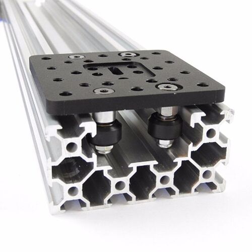
Personally, I feel like the weakest link in my machine occurs when cutting in the positive or negative Y direction, because the XZ gantry plate can rotate about the X-axis in this case. I.e., If you point your thumb either direction along the X-axis and curl your fingers in a circle this is the rotation I am talking about. Because the longmill is only supported by the 4 v-wheels in a plane, it would seem to me that adding an additional 4 v-wheels at the back of the machine might limit the type of rotation I am talking about?
Yes I understand what you mean Corey, and by the way the simulation way in the Y-direction since that’s the area of most deflection. I was surprised by it too, and to be honest there could still be a flaw with my methodology because - for instance - the simulations are mostly accounting for rail deflection not the ‘looseness’ or ‘wiggle’ that the v-wheels could be bringing to the whole system.
One thing I feel would be important to mention though is that ultimately if you consider that whatever deflection which occurs near the rail is nearly multiplied by 5 once at the cutting tool, we’re talking about limiting a very small amount of movement in order to still get a good cutting surface finish. I think adding another set of wheels behind the current set could be beneficial but you’d also have to make the profile it rides on very solidly attached as well as the way you attach the wheels would also have to be very solid. If not, since they’re both on even longer lever arms, the benefit of another line of supporting wheels would be negated by deflection in the newly extended geometry.
It’s actually interesting though that you’ve come and revived this thread all this time later because this past year I’ve actually put a lot more time, thought, and effort into further work on a more solid profile and am in the process of doing more testing in the coming months that I’m looking forward to sharing the results on 
