@aluminumwelder I like your question here.
When Andy and I originally started on the design of the LongMill we took our Mill One rail design (a simple piece of 2x2" aluminum angle) and figured we could stretch it out to increase cutting size. As testing carried forward, it became obvious that this assumption was correct for our Y-axis layout seeing as the rail could be nearly fully supported by placing the needed number of feet, however this solution couldn’t be carried over to the X-axis.
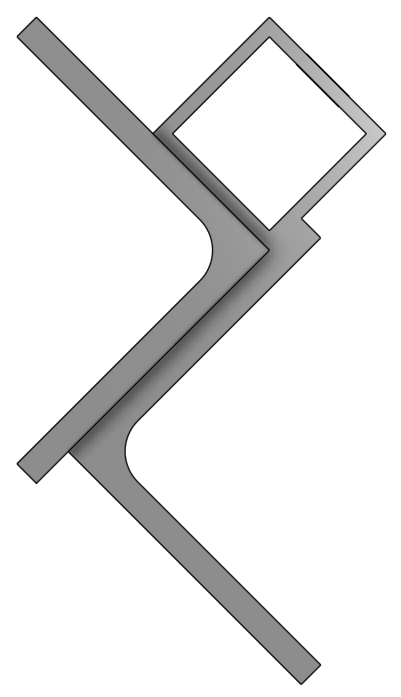
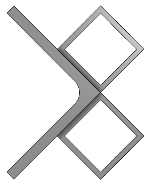
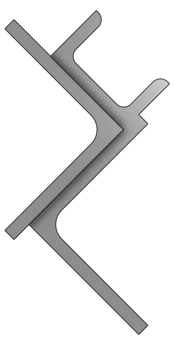
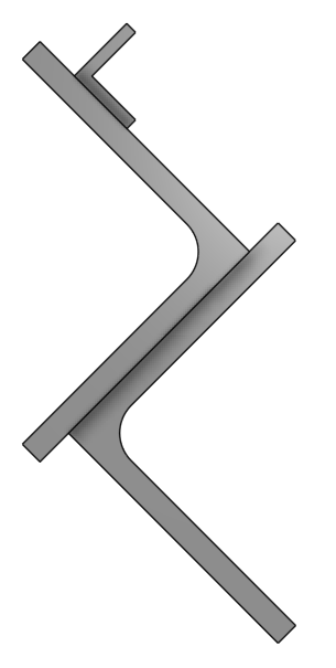
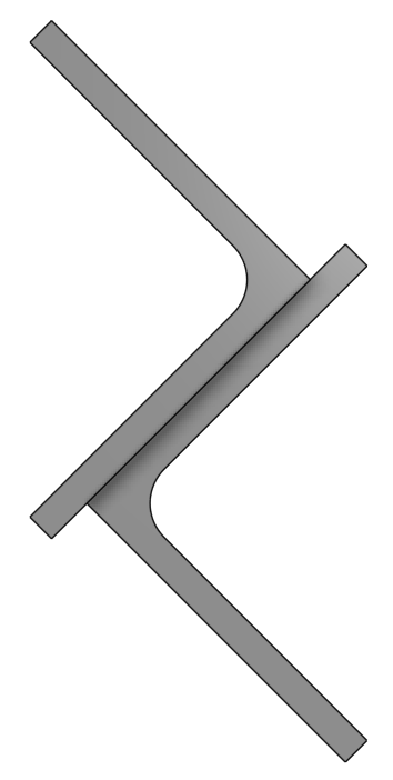
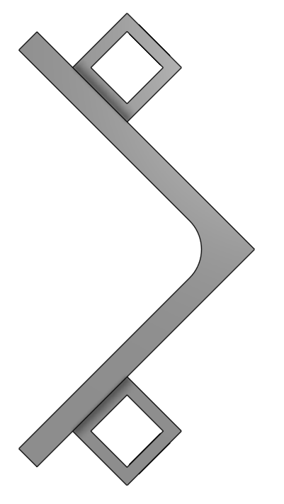
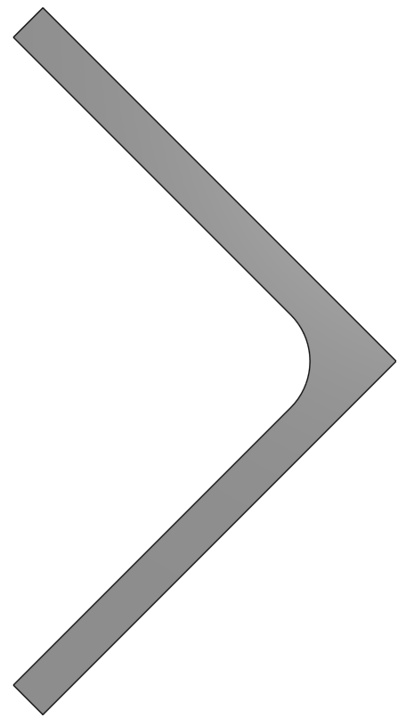
Giving it some thought, and also considering that we were nearing the end of our testing window, I realized that with the space that existed beneath the x-axis and when considering that the bottom edge of the gantry experiences slightly more force (and thus more deflection) than the top edge, I knew I could reinforce the area by adding another 3" angle since that would transfer a lot of the loading onto the perpendicular edge that the 3" angle provided. To better illustrate this, I’ll show a simulation of deflection on a single 3" angle extrusion next to one with the second 3" angle to act as a reinforcement:
Thus, the current rail layout of the LongMill was born (it’s made out of 6061 aluminum by the way). Not the most optimized design out there however it serves its purpose well. I also like that the second 3" angle forms a slight lip on the back end of the first in order to better support the drag chain.
This is where I’ll now be taking a deeper dive in my analysis since, as I mentioned, I like the question you’ve asked and I’d really like to answer it. While I was at it, I figured I’d also run the calculations for some other rail designs that I could think of which could be applied to the LongMill in its current form (although I did put the math in place to calculate it for other, completely different rail designs as well). I should preface this by saying that my original intention was to try (quite ambitiously) to solve torsion and bending in these profiles by hand, but after consulting with a good friend of mine who’s a professor at the University of Waterloo we determined that hand-solving was impossible and going the route of FEA would be required.
X-axis loading scenario on the LM: there are four point loads which act on the X-axis rail of the LongMill due to the four v-wheels which transfer load from the XZ-gantry assembly to the rail. These point loads can be a summation of a multitude of forces, but to consider the maximum loading scenario, the force due to the weight of the gantry assembly and a maximum cutting force when cutting in the negative X-direction will be considered. There are other forces which can occur such as when plunging, cutting in the Y-axis, cutting in both the X and Y-axes simultaneously, forces from a dust shoe, etc.
Since the largest twisting and deflection will occur when the gantry is at the center-point of the rail, and the v-wheel contact area is quite small, analysis will be simplified to be singular, top-and-bottom point loads since this will give the worst case scenario and will align all the important forces along an axis of symmetry, thus turning it into a simpler, 2D problem.
Problem setup:
- Longmill XZ-gantry assembly used in all simulations
- X-gantry located at center of 940mm long rail (assume fully supported at both ends)
- Z-gantry at full extension
- Router mount located in upper set of holes
- Router body extending 55mm from bottom of aluminum router mount
- ¼” cutting tool extending 30mm from router collet, making total tool extension 120mm from the bottom of the router mount to the tool tip
- The origin point of the coordinate system used for analysis is located in-line and at the mid-point between the top and bottom v-wheel contact points
- The coordinate system for analysis will reflect the coordinate system of the CNC machine it’s based within, with the X-axis being along the rail, Y-axis being into the rail, and Z-axis being perpendicular to both of these
- Rough order of magnitude calculations dictate that a worst-case scenario max load for a ¼” cutting tool which is making a deep pass at full engagement at a high feed rate through hard material would generate about 3 - 4.5kg of force or ~30 - 44N (in the +Y direction)
Assumptions:
- Entire XZ-gantry assembly is a completely rigid body
- All loads perfectly transfer to the X-axis rail via the two established points
XZ Gantry Assembly Mass:
- Makita router = 1460g
- Router mount = 300g
- Z-gantry plate = 580g
- Linear guide block = 50g
- Linear guide rail = 130g
- X-gantry plate = 1100g
- 200mm lead screw = 50g
- Pulleys + belt = 11g
- Z motor bracket = 90g
- Z motor plate = 280g
- Stepper motor = 660g
- XZ-gantry pre-assembly = 2020g
- XZ-gantry assembly (minus router) = 3680g
- Total mass = 5150g = 5.15kg ≈ 50.5N (in the -Z direction)
Preparing for Simulation
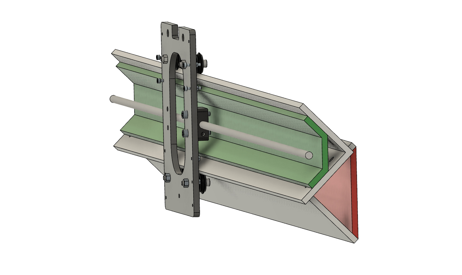
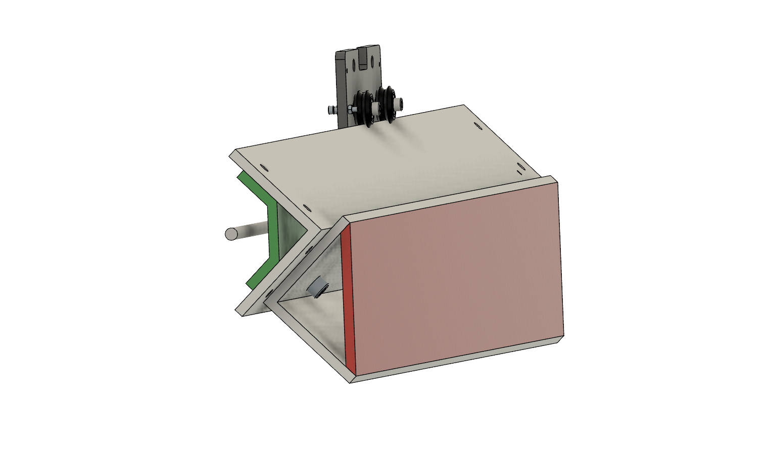
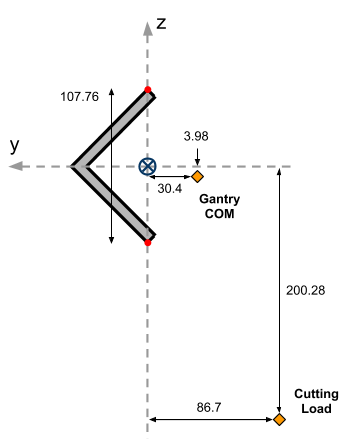
Using CAD, part layout and masses are made to reflect the real world assembly and problem setup in order to approximate the COM of the assembly in relation to the origin. The location of the applied load from cutting is also shown in the diagram below:
It’s important to note that since different rail designs will have different tip-to-tip distances then the location of the cutting load will be changed accordingly to keep a constant distance between the load and the bottom tip of the rail (bottom red dot) so that the tool stick-out remains the same. The COM location is assumed to remain the same in relation to the origin. For reference, if the Z-axis gantry were instead positioned at its highest point, the COM would shift to be ~60mm higher.
With all necessary values obtained, a Parasolid model of each rail design is brought into the simulation software and set up with an aluminum composition (E = 70GPa, v = 0.34, ρ = 2720 kg/m3), where both ends rail ends are fixed and two remote forces are applied which represent the force due to mass of the gantry assembly and the cutting force. In order to apply these forces, a small 0.1x10mm area is cut out on the top and bottom of each rail in order to create a local contact face. Since these rail designs are made for v-wheels, this small contact area is assumed to be roughly equivalent to the contact area of the two tangential faces of a v-wheel.
In some cases a simulation was run for 8 wheels rather than 4, this was laid out in a similar manner where the second set of contacting rails also has a flattened area created for the force to be applied. In the case of round rails, it was assumed that a linear bearing would be used instead, so the contact was assumed to be 20mm wide (due to the large diameter of the rails) and was indented by 0.01mm in order to distinguish it as a separate face.
Every simulation was run with the same mesh settings where the mesh was set between coarse and fine and was automatically sized appropriately.
Simulation Results
A visualization of the total displacement of each node on the generated mesh, as well as the specific displacement of each node in both the Y and Z-directions were obtained in order to understand the performance of each rail and the resulting bit deflection that would occur given the problem setup. From these visualizations, the key values obtained were:
- Maximum rail deflection
- Y deflection of top contact point
- Y deflection of bottom contact point
- Limiting Z deflection
The maximum rail deflection isn’t a very useful value since it’s mostly there to give a general idea on the performance of the rail; the maximum deflection sometimes occurred far away from the two contact points. Y deflection of the top and bottom points were important since they determine the Y deflection of the cutting tool, and the limiting Z deflection was determined by looking at both the top and bottom contact points and seeing which one would limit the overall Z deflection of the gantry assembly. Most of the time this was equal to the Z deflection of the top contact point since if the top point deflected more than the bottom, it would decide the gantry deflection, and if the top deflected less than the bottom then that would limit the gantry deflection.
With “Limiting Z deflection” being equal to the Z deflection of the cutting tool, only the Y deflection needs to be calculated. After the rail is deflected, the angle of the gantry can be approximated as such:
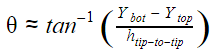
Then, assuming the gantry assembly is still in proper contact with the top contact point, the distance that the tool will translate in the Y-direction can be found:
where L is equal to the tip-to-tip height between the two contact points plus the constant, tool stick-out distance of 146.4mm. Lastly, a final optional calculation could be done to find the total deflection of the tool by taking the square root of the sum of the Y and Z deflection values, squared.
Current ranking of best rails designs based off given parameters:
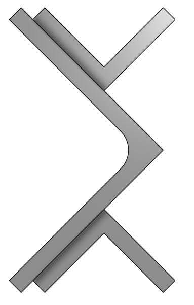
- 3” L plus 1.5” square tube (assumed holes)
- Max deflection = 0.0198mm
- Top Y deflection = -0.0101mm
- Bottom Y deflection = 0.0118mm
- Limiting Z deflection = -0.0128mm (+top)
- Y Bit movement = 0.0517mm
- x2 square tube 1.5” (8 wheels & assumed holes)
- Max deflection = 0.0235mm
- Top Y deflection = -0.0092mm
- Bottom Y deflection = 0.0173mm
- Limiting Z deflection = -0.0161mm (-top)
- Y Bit movement = 0.0625mm
- x2 square tube 1.5” (4 wheels & assumed holes)
- Max deflection = 0.0241mm
- Top Y deflection = -0.0096mm
- Bottom Y deflection = 0.0177mm
- Limiting Z deflection = -0.0165mm (-top)
- Y Bit movement = 0.0644mm
- 3” L plus 1.25x2” U-channel
- Max deflection = 0.0289mm
- Top Y deflection = -0.0184mm
- Bottom Y deflection = 0.0130mm
- Limiting Z deflection = -0.0186mm (+top)
- Y Bit movement = 0.0741mm
- ¾” L plus 3” L
- Max deflection = 0.0319mm
- Top Y deflection = -0.0205mm
- Bottom Y deflection = 0.0166mm
- Limiting Z deflection = -0.0182mm (+top)
- Y Bit movement = 0.0875mm
- Original Configuration
- Max deflection = 0.0340mm
- Top Y deflection = -0.0266mm
- Bottom Y deflection = 0.0136mm
- Limiting Z deflection = -0.0211mm (+top)
- Y Bit movement = 0.0948mm
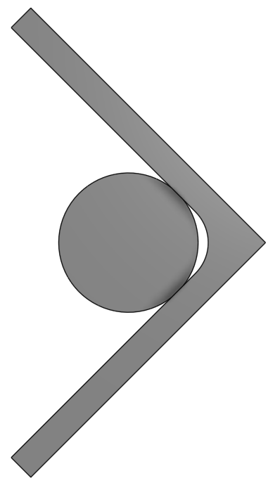
- 1.25” Solid aluminum rod
- Max deflection = 0.0372mm
- Top Y deflection = -0.0140mm
- Bottom Y deflection = 0.0303mm
- Limiting Z deflection = -0.0223mm (-top)
- Y Bit movement = 0.1045mm
- x2 L ¾” (8 wheel)
- Max deflection = 0.0489mm
- Top Y deflection = -0.0266mm
- Bottom Y deflection = 0.0386mm
- Limiting Z deflection = -0.0308mm (-top)
- Y Bit movement = 0.1538mm
- x2 L ¾” (4 wheel)
- Max deflection = 0.0496mm
- Top Y deflection = -0.0268mm
- Bottom Y deflection = 0.0386mm
- Limiting Z deflection = -0.0314mm (-top)
- Y Bit movement = 0.1542mm
- x2 square tube ¾”
- Max deflection = 0.0667mm
- Top Y deflection = -0.0374mm
- Bottom Y deflection = 0.0554mm
- Limiting Z deflection = -0.0412mm (-top)
- Y Bit movement = 0.2189mm
- Single rail
- Max deflection = 0.1317mm
- Top Y deflection = -0.0806mm
- Bottom Y deflection = 0.1001mm
- Limiting Z deflection = -0.0870mm (+top)
- Y Bit movement = 0.4262mm
So here are some of my notable takeaways to offer up from these results:
- @aluminumwelder your first design was nearly the best and your second was nearly the worst
 so I suppose that now answers your question.
- After seeing the results of some of my initial simulations, I was able to come up with a combination 3” L plus 1.5” square tube design which wound up being the most rigid! I’m very pleased with this result since it’s something that any LongMill user could add to their current machine, however I haven’t yet thought about where the drag chain would go.
- All these designs can be implemented on the LongMill, so feel free to do so. The only designs which pose an issue are number 1, 2/3, and 8/9 due to their geometry requiring that the drag chain be relocated.
- The difference in performance between 4 wheels and 8 wheels seems almost negligible when you also have to take into consideration that the connection between the front and back wheels will never be infinitely rigid (which is what I assumed in this simulation) so it doesn’t seems like it would be worth the effort.
- In case you’re wondering why none of my simulations included steel as the reinforcing material: steel (which is mostly iron) and aluminum have quite a large gap in their electron affinity which causes aluminum to behave like an anode and steel to behave as a cathode if electrons are able to move between them. If they’re left in contact for an extended period of time then galvanic corrosion will occur which will weaken and deteriorate the aluminum as well as cause some unwanted chemicalcchanges to the steel, this has been my experience at least. This is why I wouldn’t recommend using steel alongside aluminum as a reinforcement, unless you can coat either the steel or the aluminum or both to act as a barrier to stop the galvanic reaction from taking place. But even so, if you’re bolting the two together then the bolts can act as a bridge to transfer electrons between them.
If you have any comments or questions, let me know. Remember to take these results with a grain of salt since simulation is always a constant chase of trying to replicate reality even though you’ll never quite reach it. The results are more to be used as a way to compare rail designs to one another, not as a reflection of deflection you’d see in practice. I also want to once again emphasize that I tried to set up the problem for the most extreme loading case, so also take that into account when you’re looking over the deflection results.
Anyway, I think that about wraps it up for me. Cheers,
Chris

 . Proof positive that proper analysis beats seat of the pants engineering every time.