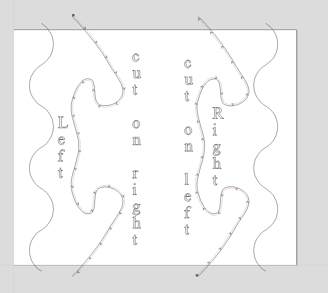
So next I wanted to get a bit adventurous because I’d like to be able to mate different shapes, whatever I want is the goal, like the vase with two faces etc.
Using the same stock left over from the first test. The new line on the left is the original. I offset that line by .15mm to the right. I then moved the offset line to the right.
@_Michael A lot of this is trial and error. I’ve done several jigsaw puzzles and I use an offset to get the pieces to fit snug but not tight. The offset changes depending on the thickness of the material. I guess it’s just a friction thing.
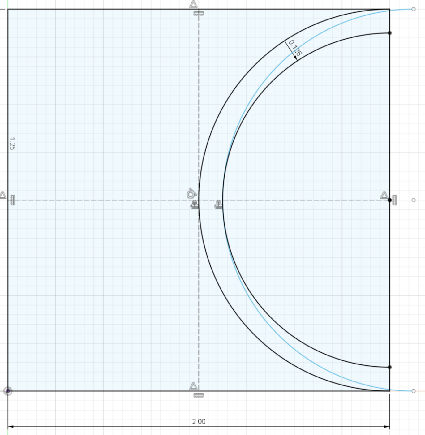
I had some time to draw up what I think the problem is, by what I’m hearing - haven’t been out to the garage to cut anything, but this looks to me like the issue that is happening.
In this sketch, you can see a base curve (the left one) and two “offset” curves - one is offset radially by 1/8 inch, one is offset linearly by 1/8 inch.
Since I use Fusion, I don’t know the process for determining toolpaths that you are using - with Fusion, I select the feature and the bit diameter and it does the rest to determine what path the bit should take. You can see in this case, the path that the bit needs to take is a radial offset (that is, the diameter the toolpath actually takes is different than that of the feature we are dealing with). If we were to offset only linearly (that is the blue line, which has a 1/8 offset in the x dimension), you can see the bit follows the same arc as the feature (the left black line), but because of the bit’s diameter, the cut ends up having a different shape.
Can someone confirm that my impression of how your toolpaths are being created is correct? I can confirm 100% that Fusion would cut the right hand black arc, resulting in the shape of the cut that you ultimately expect. This would then cause even more issues for more complex and variable shapes.
Hope that leads to more success - and I do want to get into the garage, but we just had a new arrival and things are of course busy!
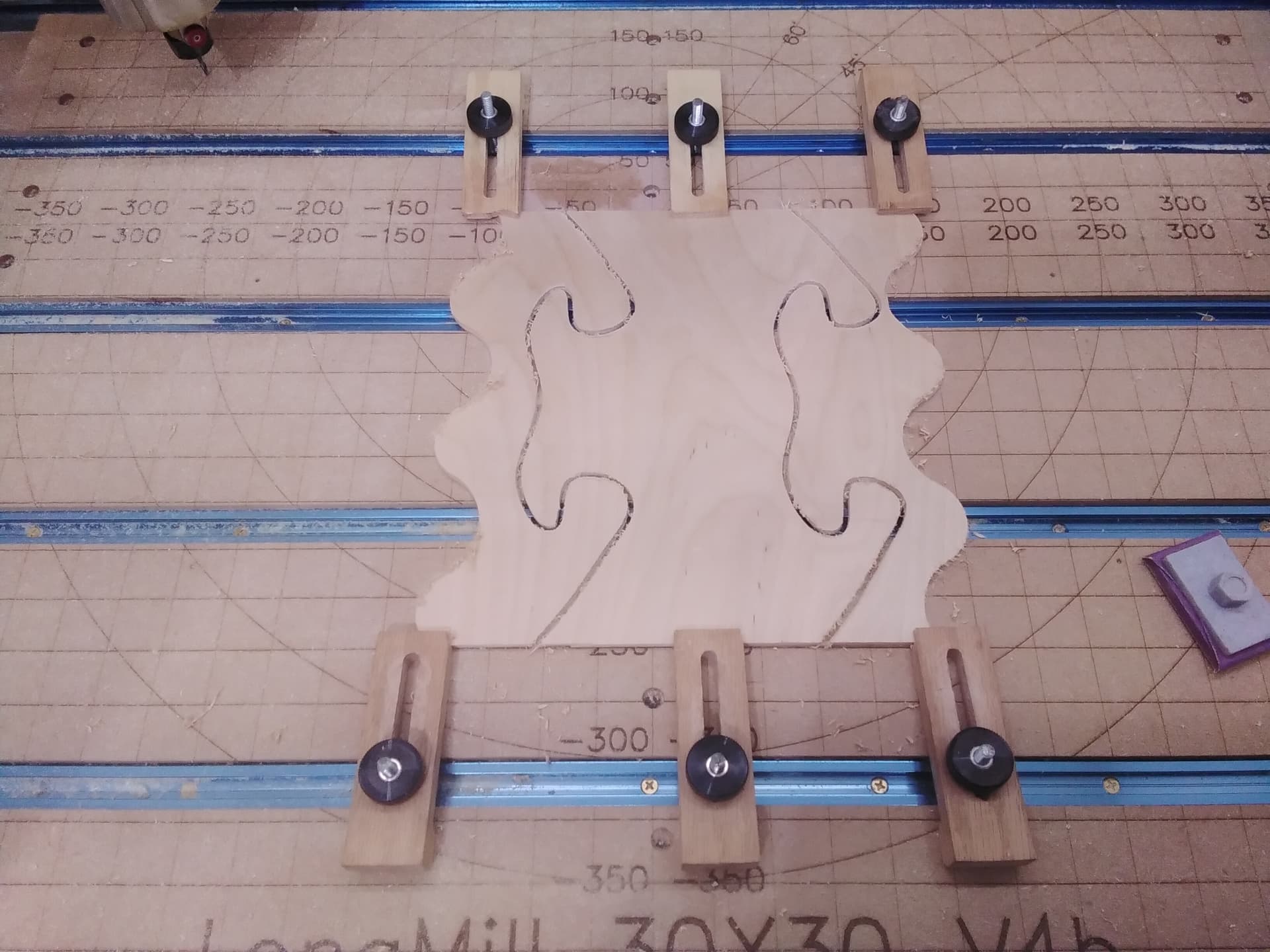
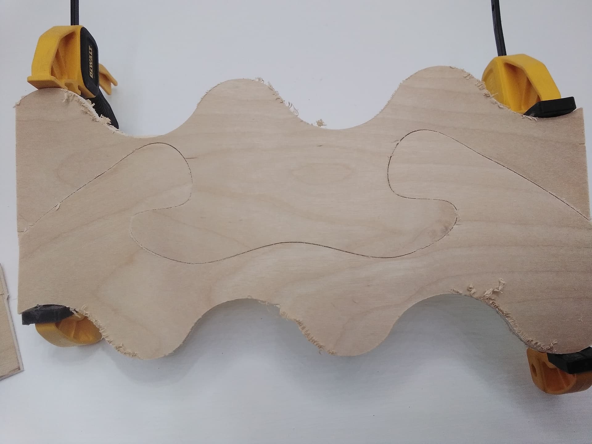
So I just finished my second set of test cuts utilizing Grants process as detailed in his above post, I have to say the pieces fit flippen amazing on both tests, I mean perfectly, so hats off to Grant for coming up with that.
My 1/4 end mill was out also, made the necessary adjustment for that and the rest was somewhat easy once I got my head around it, basically using 1 vector for two cuts on two pieces of material. Tomorrow will be the real test on the actual pieces of walnut & purple heart I will post my results, positive ones I’m sure with some pic’s if all goes well.
Thanks again for all who provided their help, much appreciated.
@Brunom I’m glad that it worked. Keep in mind, though, that this was a solution to address your specific problem. As others here have said, if the profile of the cut changes, you may need to look further. For example, when doing jigsaw puzzles, the simple approach to your issue will not work. You must build in some tolerance/offset or the pieces will not fit together. It’s the same concept when trying to put a 2" peg into a 2" hole. Can’t be done. If you want to read more about the concept, looks into interference fits vs clearance fit. For jigsaw, we need a clearance fit.