Hi everyone, having an issue with matching mating curved profiles. The parts align perfectly in the middle of the curve but are out by about .005 on both ends, I’ve tried inside the line on 1 and outside the line on the other, on the line for both is close but not perfect. I’m thinking this shouldn’t be all that difficult and that I’m missing the obvious to correct the problem. Any help and or advise would be greatly appreciated. I’m running VCarve Pro latest edition.
I should clarify, I said in my previous post the profiles were curved, I should have said the two matting profiles are arced, hopefully this gives a better understanding of my issue, thanks
Hello and welcome @Brunom - not sure I can point straight to your problem, but maybe I can help get things started. For reference, I’m a Fusion 360 user, but I think the problem could happen in either package.
Can you post a screenshot and/or image of what you’re dealing with? By my understanding, it sounds like two identical curves that aren’t identical, but I can’t really picture how you’re getting there. Also, how big are the parts, and are the arcs oriented the same way when being cut?
Hopefully we can get you sorted - looking forward to seeing what you make!
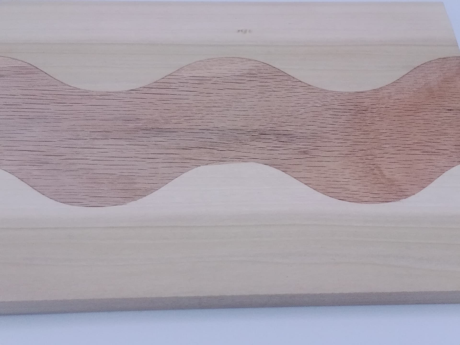
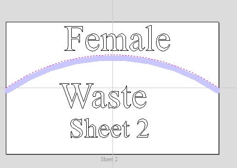
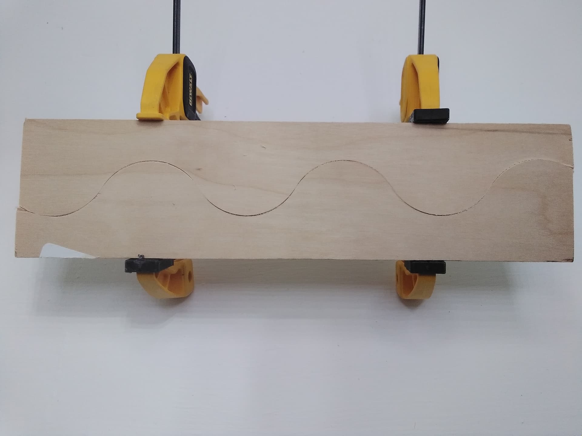
Are you trying to make something like this “wave” that a made for a box lid?
Not sure what you are using for CAD/CAM but I did this with VCarve Desktop. I used the offset feature to create the second curve that matches up with the first. This may be hard to explain or follow but I’ll do my best.
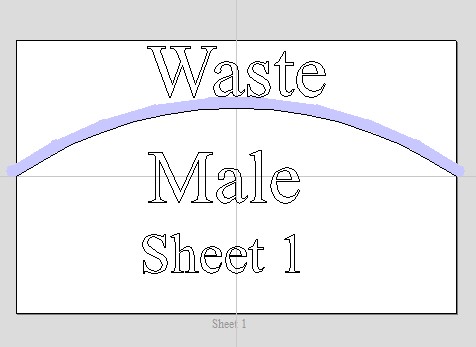
This piece I made has 2 curved joints but lets focus just on the top one. First I entered the boards that I was going to use on separate sheets. Then I made the curve on the upper board and that one would be cut on the lower side. Then on the upper board I made a curved line using the offset feature set for 1mm, making this line lower than the first line. I then copied this second line to the lower board sheet and cut it on the upper side.
I hope that kinda makes sense and I think I got pretty good results. If if you have more questions on my method feel free to ask.
@Brunom This video does not cover CNC use, but you will see why you are having the problem. That may lead you to a solution.

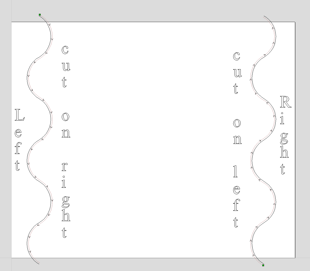
I just drew this up in VCarve and I think it illustrates the problem with just cutting one on the left and one on the right.
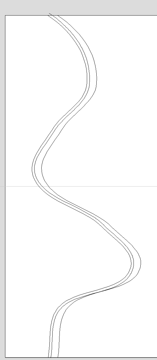
In the picture the line on the left is the original curve, the middle line is offset 1mm using the offset tool. The line on the right that looks all wonky is a copy of the original.
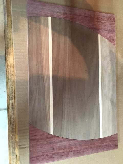
Hi Michael, thanks for your reply. So ya I am trying to make something similar to what your picture shows. I have attached some pic’s which should give you a much better idea then my explanation. I’m thinking that some sort of off-set is the answer but I’m not 100% sure of how much, seems to make sense the offset would be either the full cutter width (1/4) or half the width dependent on where the toolpath runs. Where did you come up with the 1mm offset on your piece. Anyways if you can have a look at the pictures attached and send along any additional comments or thoughts it would be appreciated.
Hi Ed, thanks for your much welcomed reply, I have attached a few pictures, as for the size the end caps are approx. 4.5x11 and the main board is 14.5 x11. The arcs are orientated the same way when cut. After some frustration I did a test cut, I took the tool path and a single board, ran it hoping that I might use the two pieces as templates for a flush trim bit on the router table. The pieces did not fit, so I’m figuring I have to compensate for the ¼ end mill, but I’m not certain.
Anyways I hope the pic’s will explain a little better of what I’m trying to do, thanks in advance


Thanks for your reply Grant, I’ve watched some of Stubbs video’s ( at least I think that’s his name) in the past. I believe I see the problem that being I have to compensate for the ¼ end mill bit. So as I see it cutting 1 piece on the outside of the line and then off setting the second piece by ¼ should produce what I’m trying to accomplish. Would you agree
I just pulled it out of the air, that curved piece was my first non-practice try. Maybe an even smaller offset would work better? I think I am on the right track with the offset method, but we always think we are on the right track or we’d be trying something else, right!
The video that Grant linked seemed like a good way to do it but I’m not sure how to translate the router table method to a CNC machine.
Ya the video Grant linked was good. I’m thinking if nothing else I could make the templates on the cnc and then cut the profiles on the router table using the method in the video. Not giving up on doing the matting profiles on the cnc just yet,
I might be stretching my knowledge a bit here, since I usually use Fusion 360 - but typically I would model this as two mating parts, and the tool offset would come in automatically in the toolpath generation (based on the radius of the 1/4 inch bit itself). I would expect any offset error to come from any differences in the nominal bit diameter vs the actual - and measure it with calipers to adjust.
Thinking about it - the tool offset needs to be a radial offset (that is, perpendicular to the tangent to the curve at every point), as opposed to a linear offset (i.e. offset in just the X or Y dimension). In my head, that would probably cause the effect you are seeing.
Sorry I can’t be more helpful with VCarve Pro - I’m not familiar with how it generates toolpaths.
I think the free version of Fusion 360 can still do what you need (2.5D milling) according to this: Changes to Fusion 360 for personal use | Fusion 360 | Autodesk Knowledge Network
The learning curve for Fusion can be really huge, but it might be worth investigating for specific needs.
Good luck!
Thanks to all that replied, much appreciated and it has certainly given a better understanding of the problem and corrective solution(s). I plan on somewhat starting fresh making new end pieces and using a combination of your suggestions on some test pieces until I get it right. Will post with my results one way or another, here’s hoping their positive results.
thanks again B
@Brunom I apologize for the long delay in adding to the discussion. I have an idea on how to do this, but I will try it in the shop before posting - to save me the embarrassment of being wrong. I hope to do that early tomorrow and will post my results.
@Brunom OK, finally, I got this done! I see that you posted on the Vectric forum, too and I’ve posted my successful project on there as well.
I’m attaching two screencaps of the tool paths that I cut. The two pieces mate perfectly. A couple of things that I found:
- The actual diameter of my “1/4” downcut end mill was not .25". It was .2460". Not a huge variance, but enough to make a difference I think.
- When I was doing the test cut to find the diameter of the bit, I noticed that, when taking more than one pass, there was a very slight ridge or step in the groove. When I repeated the test cut in only one pass, there was no step (duh). Clearly, if you are taking more than one pass - and that is a must on thick material - there is a chance for bit flex, machine flex, etc, that could throw off the arc by a very small amount.
Anyway, FWIW, there is the solution. I don’t believe that there is anything more that I can do on this, but if any of this is not clear, post back.
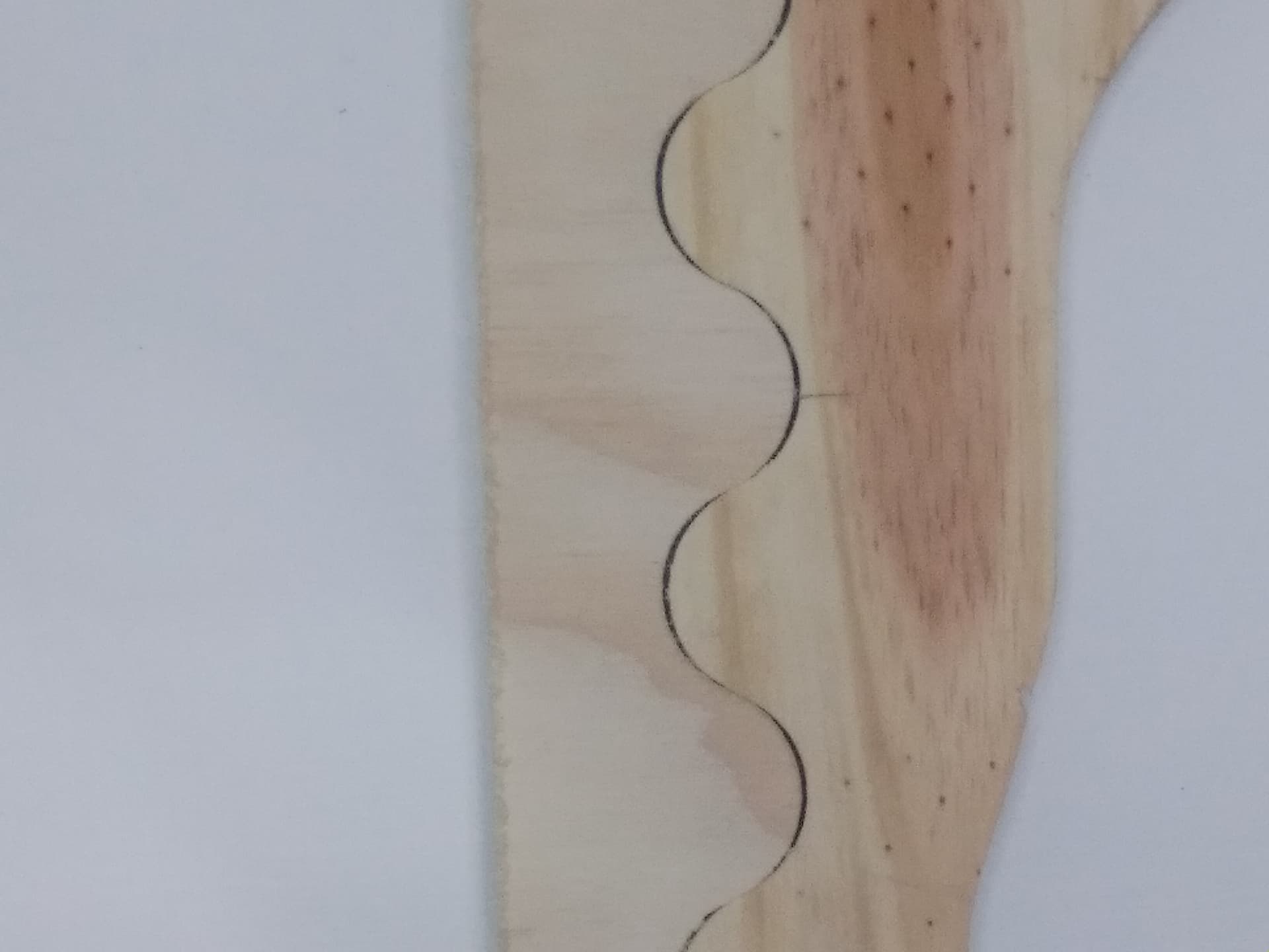
Glad that worked out Grant and I hope that’s all @Brunom needs to do. I’m now wondering if it makes a difference if you have one curve vs multiple curves. I cut the pieces in the photo like you did, one cut on one side of the curve and one on the other. As you can see they don’t fit well at all. I think the problem is the farther the angle of the cut deviates from the main direction of the cut the more it binds. For example in my photo the main direction is vertical and it’s where the pieces go fairly close to horizontal that they touch first.
Maybe I did something wrong in my test and I might try to it again. If you have time and scrap maybe you can try it too. Please don’t waste any good wood on my account!
@_Michael Were both of those cuts done from the same board?
I’m not sure, probably not as I picked them from my scrap box, they are the same thickness.
Edit: I found a thin piece of plywood scrap and I will run the test using the same board.
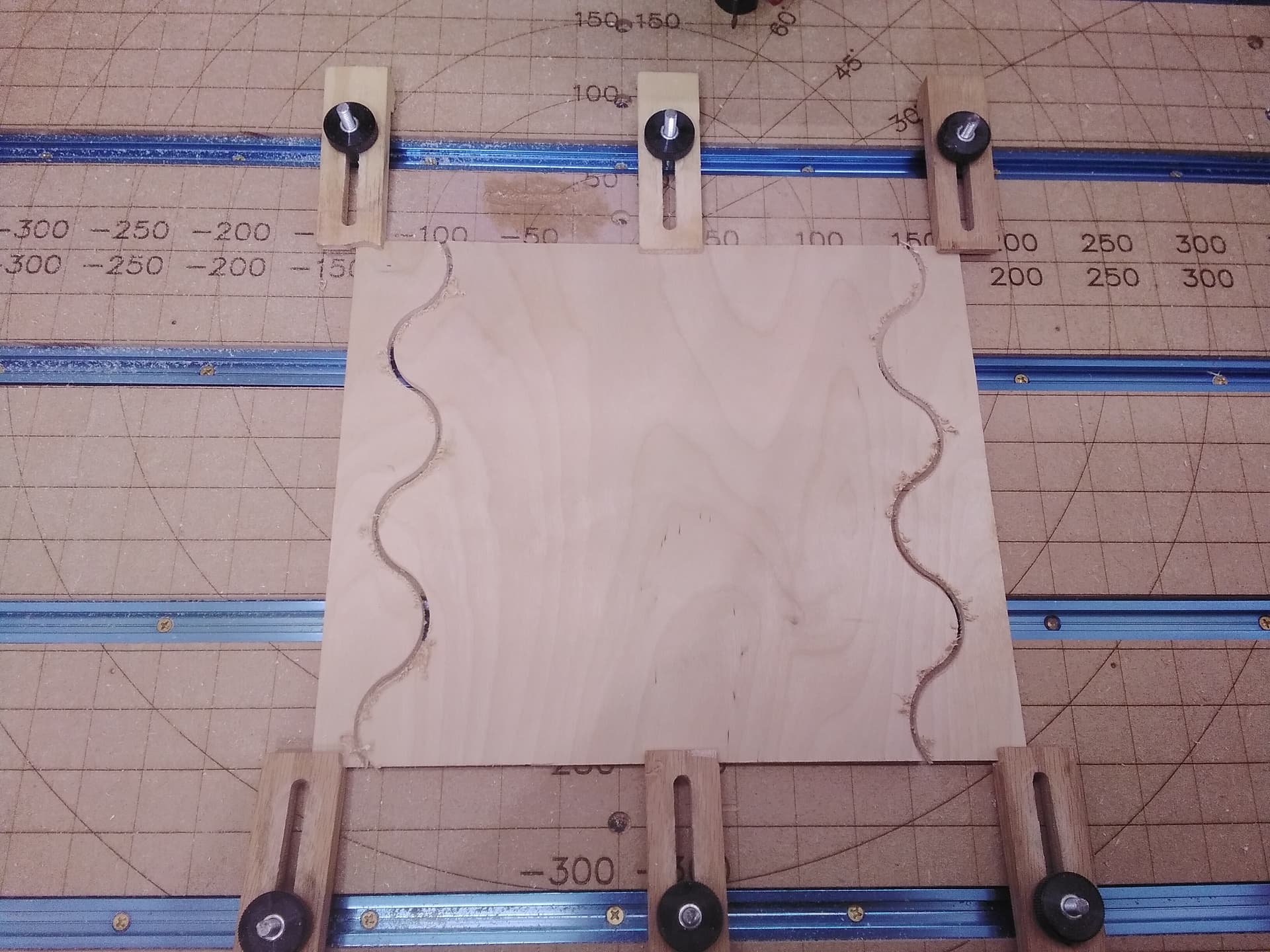
@_Michael Running them from the same board may be the problem, Michael. By that I mean that if you are doing that, you need to have the design drawn twice. I did my test on the same board, but drew the arc, then copied it, then created the toolpaths - one on either side of the line. I did not try to offset at all.
I hope that I’m making myself clear. When I get time, I can try your design, but I’m pretty confident that my “process” will work.
I think I understand your “process” because it was my first though on how to do it as well. I ran the test again and got the same results.
As you can see they still touch at the ~45 degree part first. Believe me, I really wanted your process to work because it is simple and simple is always better if it works IMHO. It was these results that led me to try the “offset method”. I think of it like needing a tolerance, like when I do dovetails, the pins need to be slightly smaller than the tails in order to fit.
I cut these with a 1/8" or 3.175mm bit with a 1.4mm pass depth at a speed of 17mm/sec or 40inches/min which I believe to be conservative.