A day of greatness indeed! Now more waiting game for you 
Not really, but thanks. I got my LongMill 2+ years ago, and been reading here ever since is all.
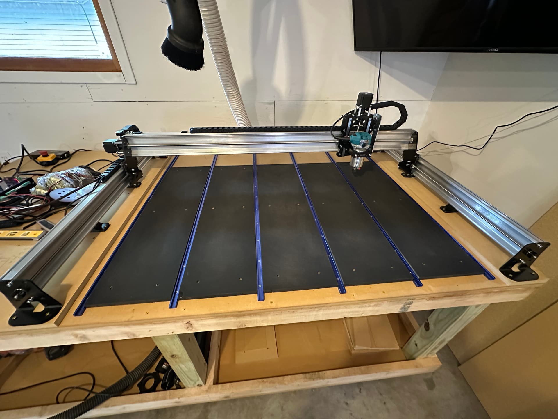
This is how I made my setup. First I made the table, 2x4 construction as straight and square as I could. Which for me meant building it on the concrete floor and hoping that was good enough. My mill is on the left side of my table so when I figured out where the front left foot should be, I used a straight edge and square to mark an L. I attached the left front in the corner of the L and the rest of the left feet touching the line. Then with the X rail forward I mounted the right front touching the front line and as I moved the X rail back I attached each remaining right foot.
If I had to do it over I would most likely try the method where you mount the mill to strips with a slot and bolts for adjustment. Even when drilling the holes for mount screws first it was easy to mess up the placement by over tightening an angled screw. Not sure if the MK2 screws go straight down or not but some of the MK1 ones are angled.
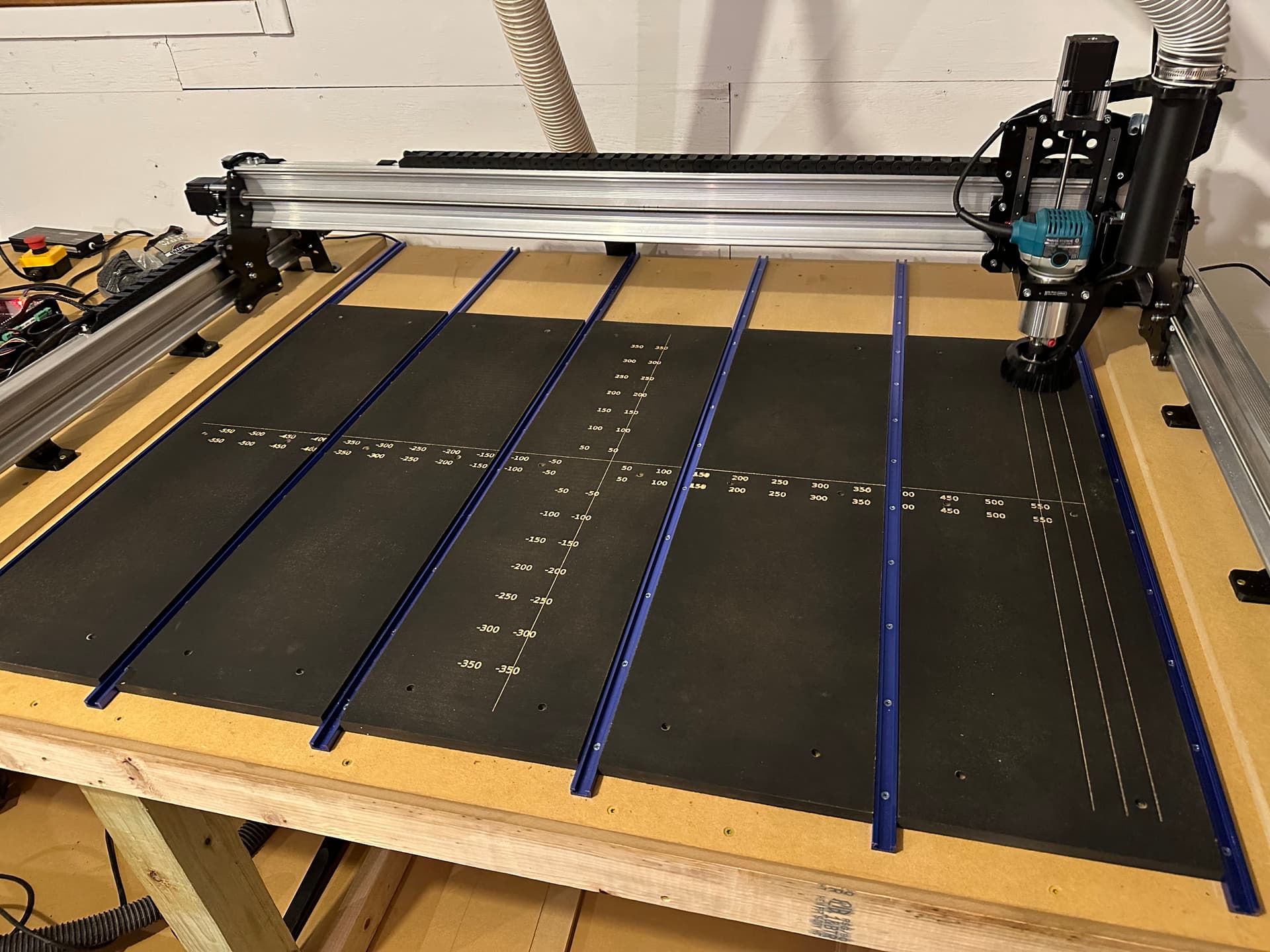
After mounting the mill I jogged to the 4 corners and marked the bit center for each corner. The t tracks came in packages of 4 and I didn’t think 4 was enough so I bought 8 t tracks. With the number of tracks, strips, and the area to cover known it wasn’t too hard to figure out the spacing. The strips ended up being being about 4", they aren’t exact, I ripped them on a table saw. I marked lines for the t tracks and installed them first. With t tracks mounted I was able to clamp the strips so I could mill the counter sunk screw holes for attaching the strips. I made one program and ran it in the same place 7 times switching out the strips each time.
The spoil board I made actually covers more area than the center of the bit can reach. That’s okay as long as you can reach the edge of the spoil board with your surfacing bit. You want to be able to surface the whole top of the spoil board in case a work piece needs to extend off from it, for pass through work etc.
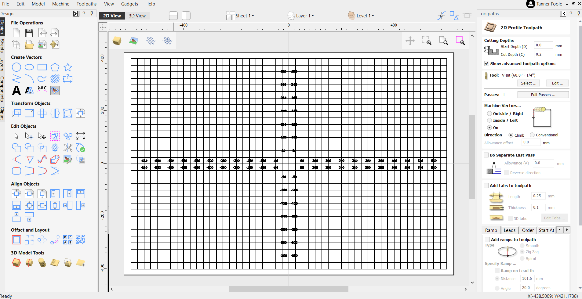
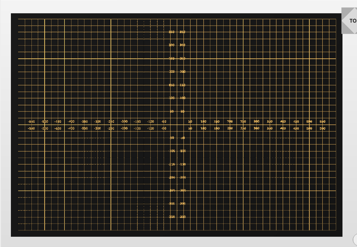
The grid was done last with my laser. Since it was done last with everything mounted it is square to the mill. I needed to make a mount so I could put the laser in the center of the router mount so the laser could reach everywhere. I took this opportunity to cut the cable on my router and put in some connectors, one each way so I can’t plug it in backwards. Then I put connectors on a salvaged cord so I can use the palm router off from the mill if I need to.
The main use for the grid lines is just to place work pieces square to the mill easily. Before I had the lines I would put a board touching the bit at the front and then while holding the front, jog the machine back and move the board to touching the bit, hoping I didn’t move the front etc. Now I just take the straightest edge and place it touching the line and clamp away. The touch plate will find a corner but it won’t make sure you mounted the stock material square if your trying to use all of it. Being mounted super square may not matter if your not using the edge of the material. But wood is expensive now a days and I try my best to use as much of it as I can.
As far as the direction of the t tracks goes, I think it’s just user preference. I knew I was building an enclosure, primarily to keep the laser fumes contained/exhausted, and that I would not have access from the sides so that dictated the t track direction for me.
Long read, I know, hope some of it’s useful!