This a guide on how I make dovetail joints on my LongMill. I’m posting it so I don’t forget how to do it and to help others. Even if you have VCarve Pro I think my way offers more freedom to do different sized tails or odd spacing etc. that I don’t think the gadget offers.
I will be using Vectric VCarve Desktop but my method should be applicable to other software and machines as long as you have a way to mount boards vertically.
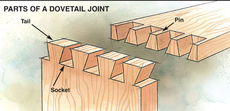
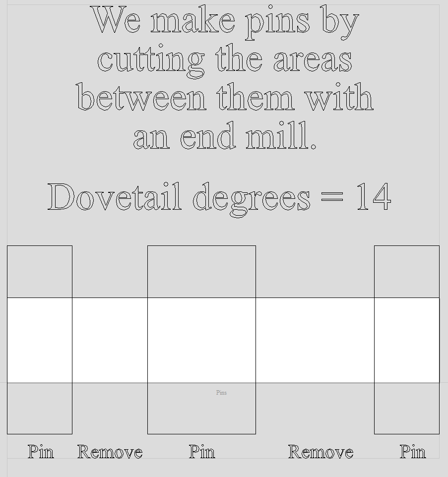
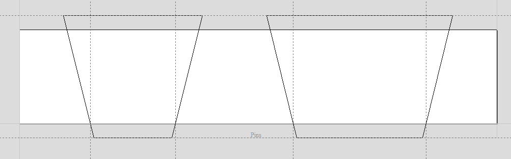
First off so we are the same page with terminology here are the parts of a dovetail joint.
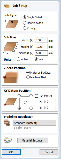
I design the tails and sockets and then the pins. So I have two sheets in Vectric and the stock is the same size for both, at least from the end view of the boards. I’m going to use some MDF scrap I had laying around. It is 100mm wide, 19.6mm thick and the length doesn’t really matter as long as we can clamp it.
I will be using a 0.75" (19.05mm) 14 degree dovetail bit and an 0.125" (3.175mm) end mill. The cutting height of both bits needs to be greater than the stock thickness.
So here is the job setup in Vectric. Notice that the thickness of the stock becomes the height and the length becomes the thickness because we are looking at the end of the board.
The strategy for making the tails tool path is to make a long continuous vector that is the path I want the bit to travel along and then use a profile tool path, on the line, with a cut depth the thickness of the stock in one pass.
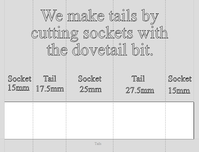
This is my layout for the tails and sockets. I have placed guide lines that represent the spacing of the tails and sockets 19.6mm, the thickness of our stock, below the surface. In other words the narrowest part of the tails and the widest part of the sockets. I have chosen to make two different tail sizes and two different socket sizes because I can!
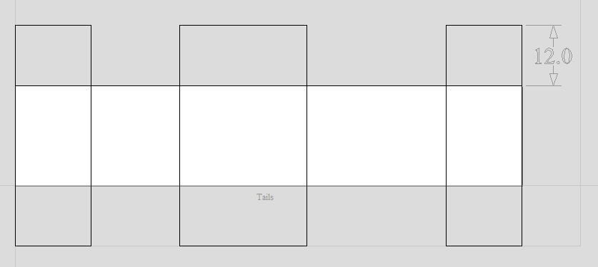
Because I will be using many guide lines, and it can get confusing I make some rectangles that represent the area to remove. Notice that I extended them of the stock by more than half the bit width. That’s just so I can snap a guide there when I need it.
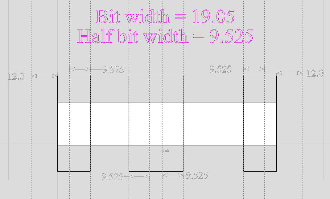
The next step is some more guide lines! The inner guide lines are half the bit width away from where we want the cuts to stop and the outer two are greater than half the bit width away from the stock.
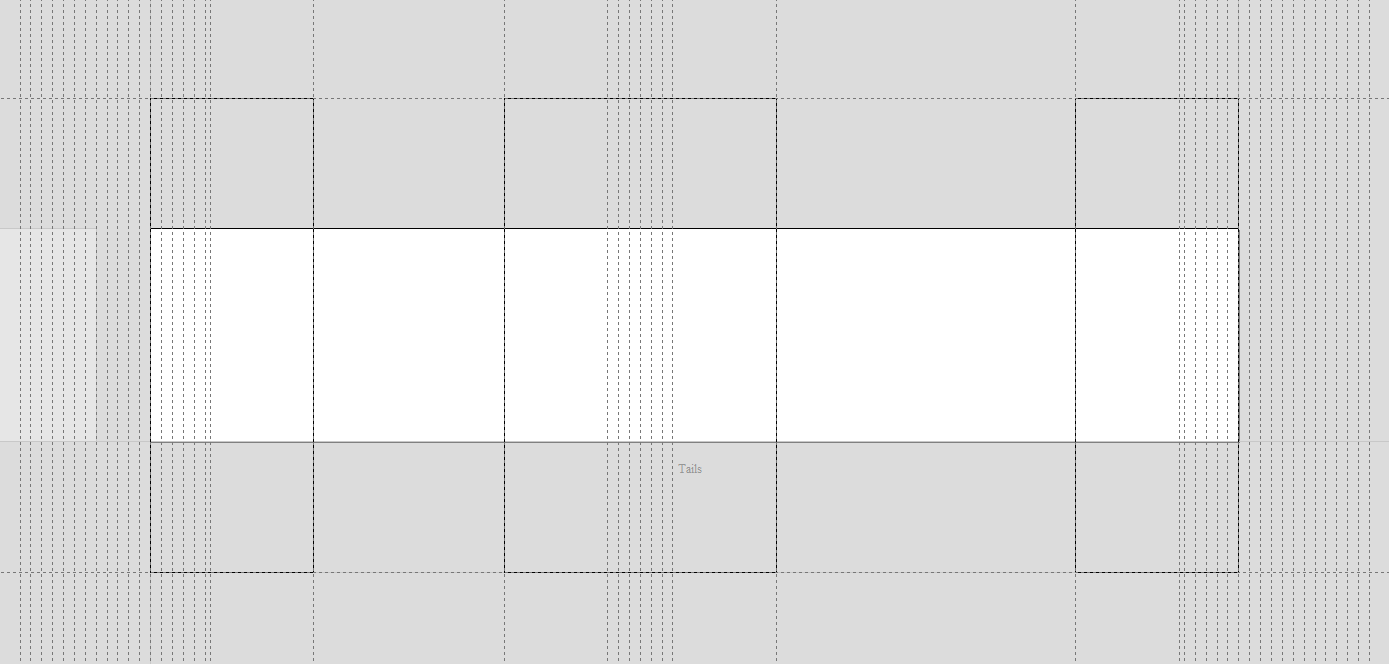
After that I need, you guessed it, some more guide lines. These guide lines are like the passes in a normal carve taking off more material with each line.
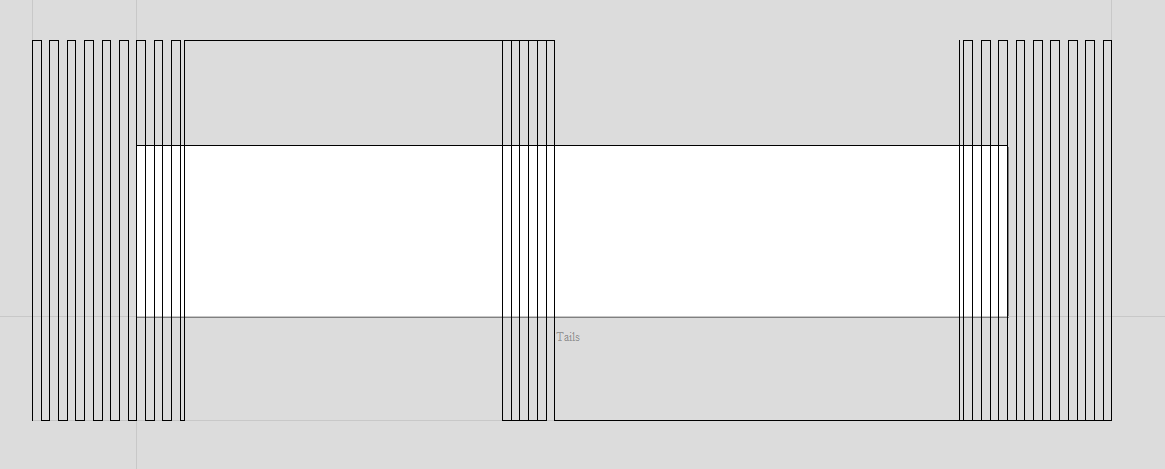
Next I make the “tails tool path vector”. It starts at the lower left moving up and down each of the guide lines on the left. Then after it exits the stock it goes to the middle of the center socket and goes through the stock in a spiral pattern until all the center guides are used. Then it goes to the far right and works it way back to the left until all the right guides are used. When it does the center socket it will do a full bit width and depth cut so I need to use a slow feed rate. If you wanted you could use an end mill to clear first but you have to remember that the sockets narrow towards the top so you can’t clear the whole width. You can use some trigonometry to calculate the width at the surface if you want to make a roughing pass.
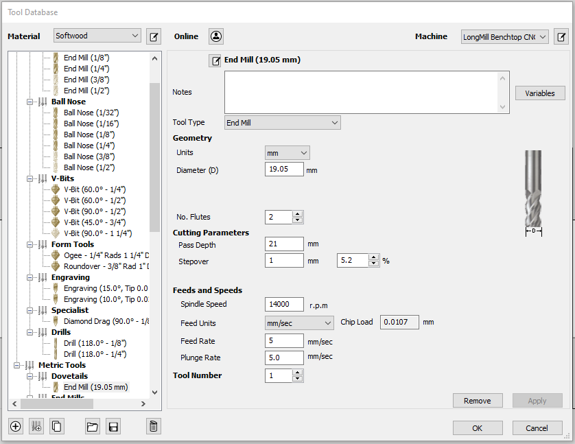
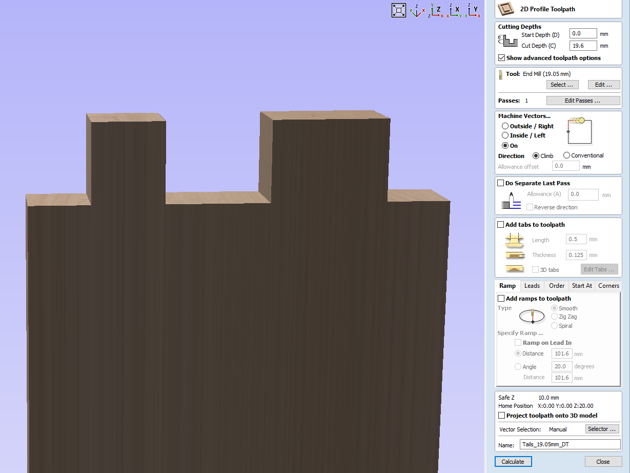
Now I am ready to make the tool path for the tails but first I need to set up my bit. Vectric doesn’t have a dovetail bit so I use the end mill tool type. The important settings are the diameter, pass depth and feed rate. The pass depth needs to be greater than the depth of cut so that Vectric will do it in one pass. The stepover doesn’t matter, that’s what all those guide lines were for. I used a very slow feed rate of 5mm/sec. That’s about 1" in 5 seconds for the metrically impaired. ![]()
Now I’m finally ready to make the tails tool path. Notice that it looks like a box joint because Vectric thinks it has an end mill.
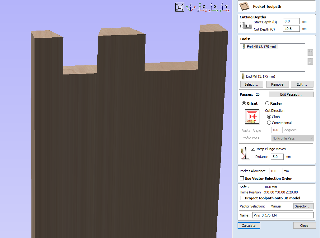
Now I can move onto the pins which are a little easier. The strategy for making the pins is to pocket out the areas between them.
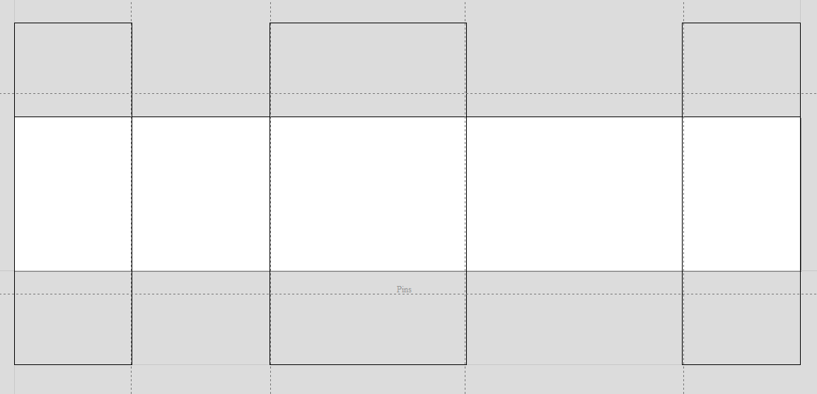
I start by moving or copying the rectangles from the tails sheet to the pins sheet.
The guide lines for making the pocket vectors. Notice that the vertical ones are moved into the rectangles slightly. This is the fit tolerance, I moved the guides into the rectangles by 0.15mm and that gave a good tight fit. The horizontal guides are 3mm off the stock. They need to be off the stock by at least half the end mill diameter.
Now I can start to lay out the pocket vectors. I don’t know the width of the pocket 3mm of the stock, I only know it at the edge of the stock so that’s where I start my vectors. The dovetail bit is 14 degrees so I make the vectors 14 degrees from vertical, that’s 76 degrees. I also throw down some vectors for the top and bottom of the pockets.
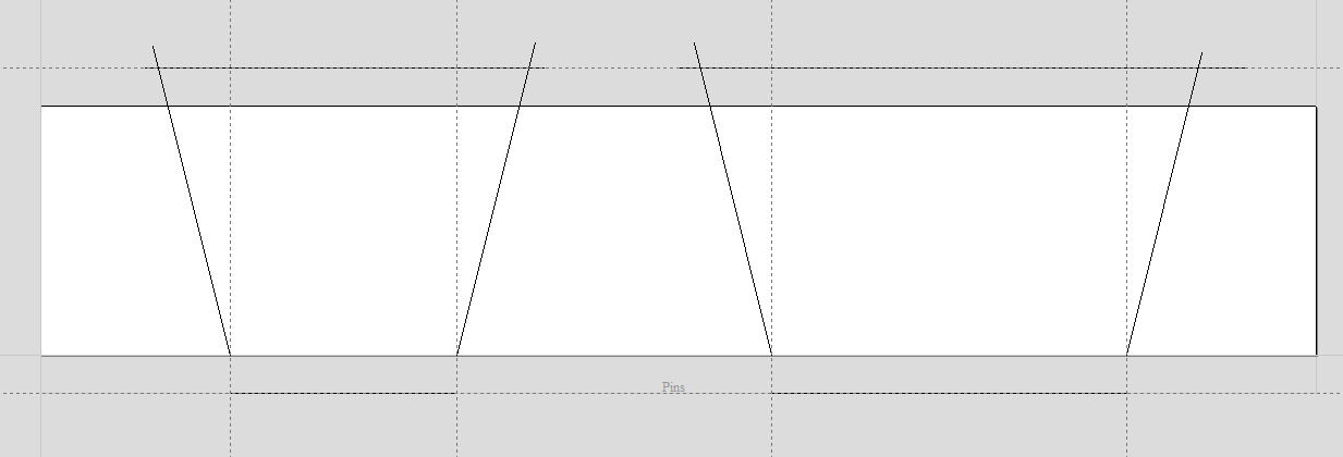
After using the extend vector tool and interactive trim I have the pocket vectors.
Then I can make the pins tool path and preview it. Because it uses an end mill the preview looks correct.
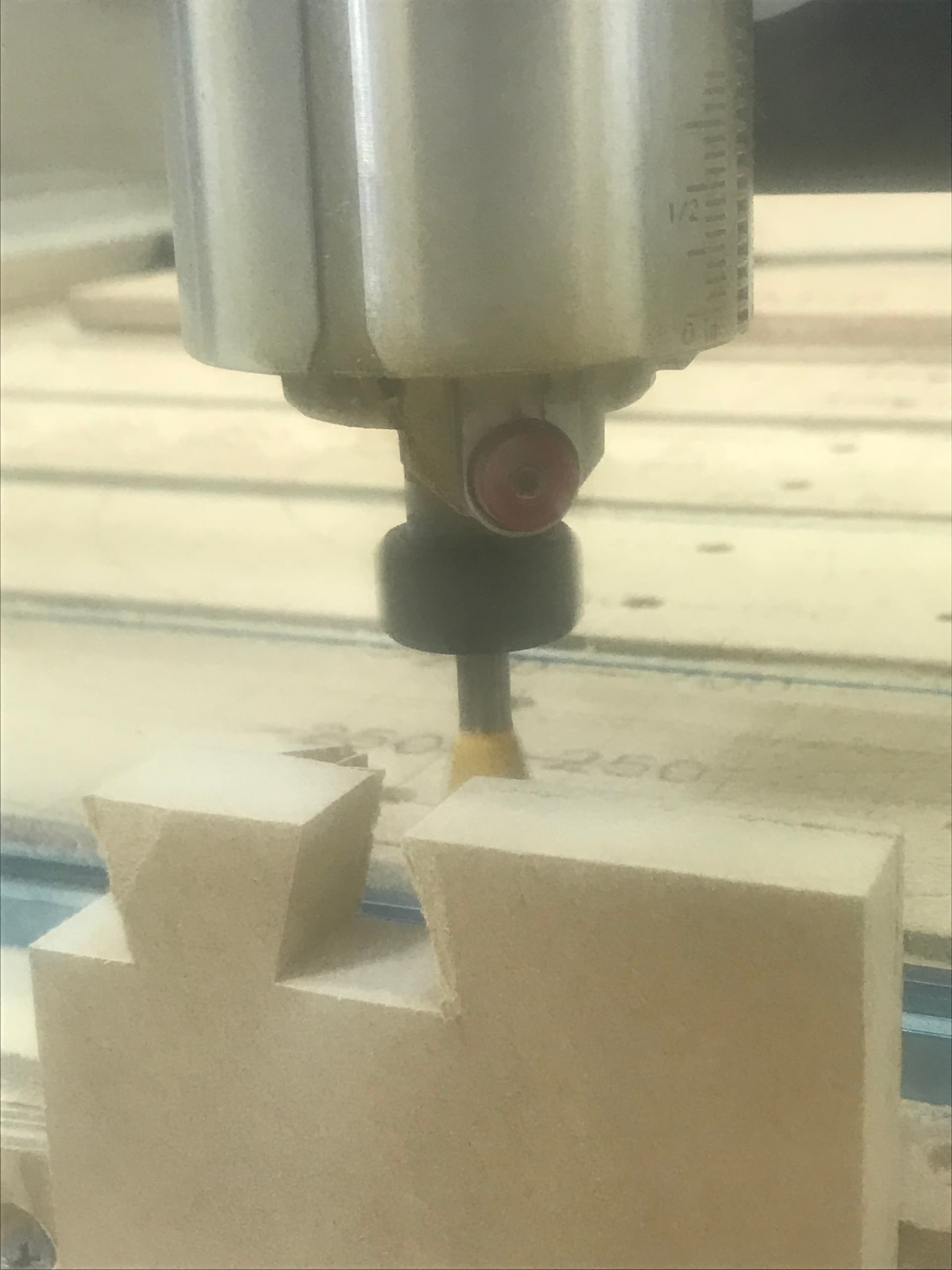
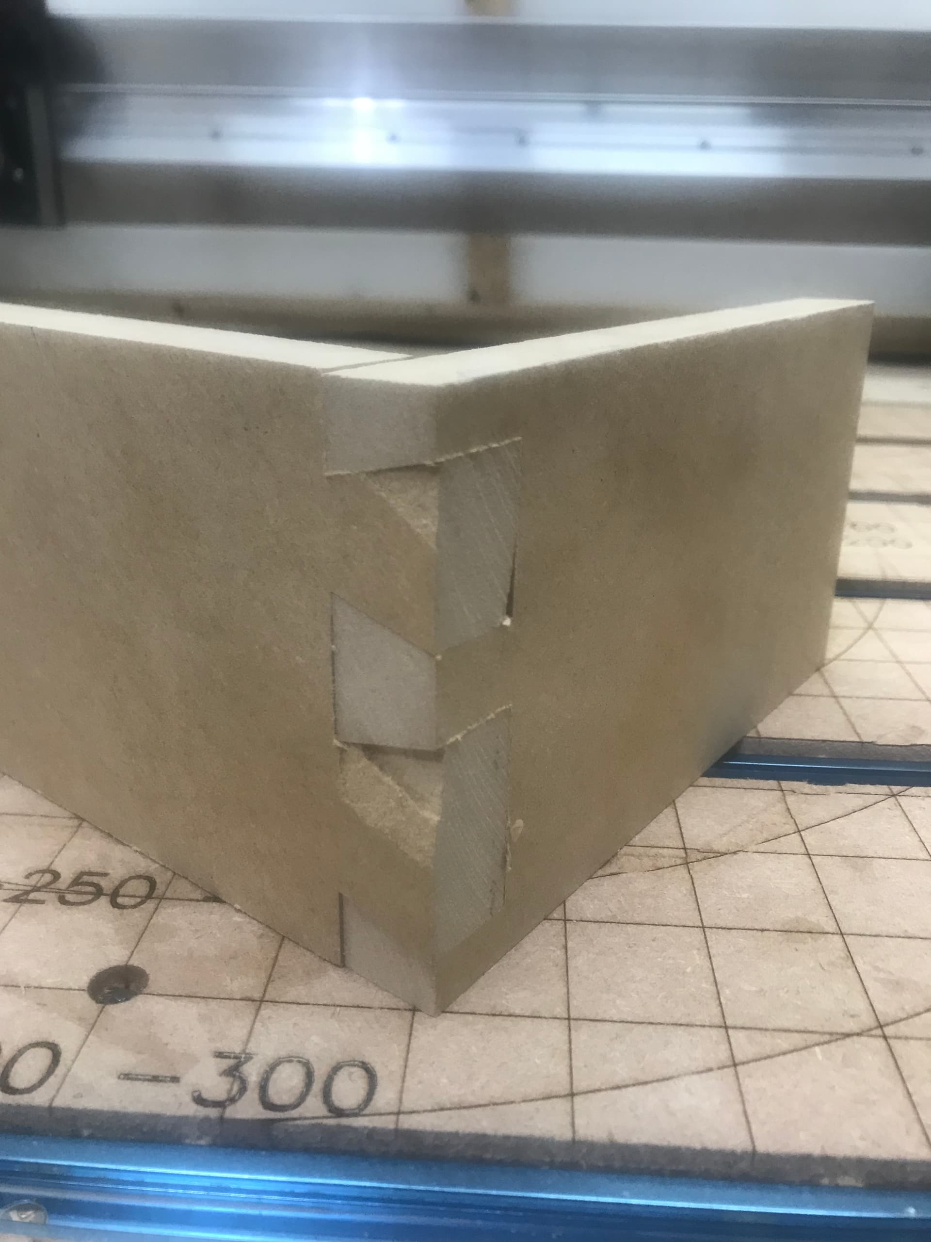
Now it’s time to carve! Unfortunately the MDF tore out quite a bit on the tails carve. I wonder if taping the ends would help with this. I’m open to suggestions on how to reduce tear/chip out with MDF and wood when milling the end grain.
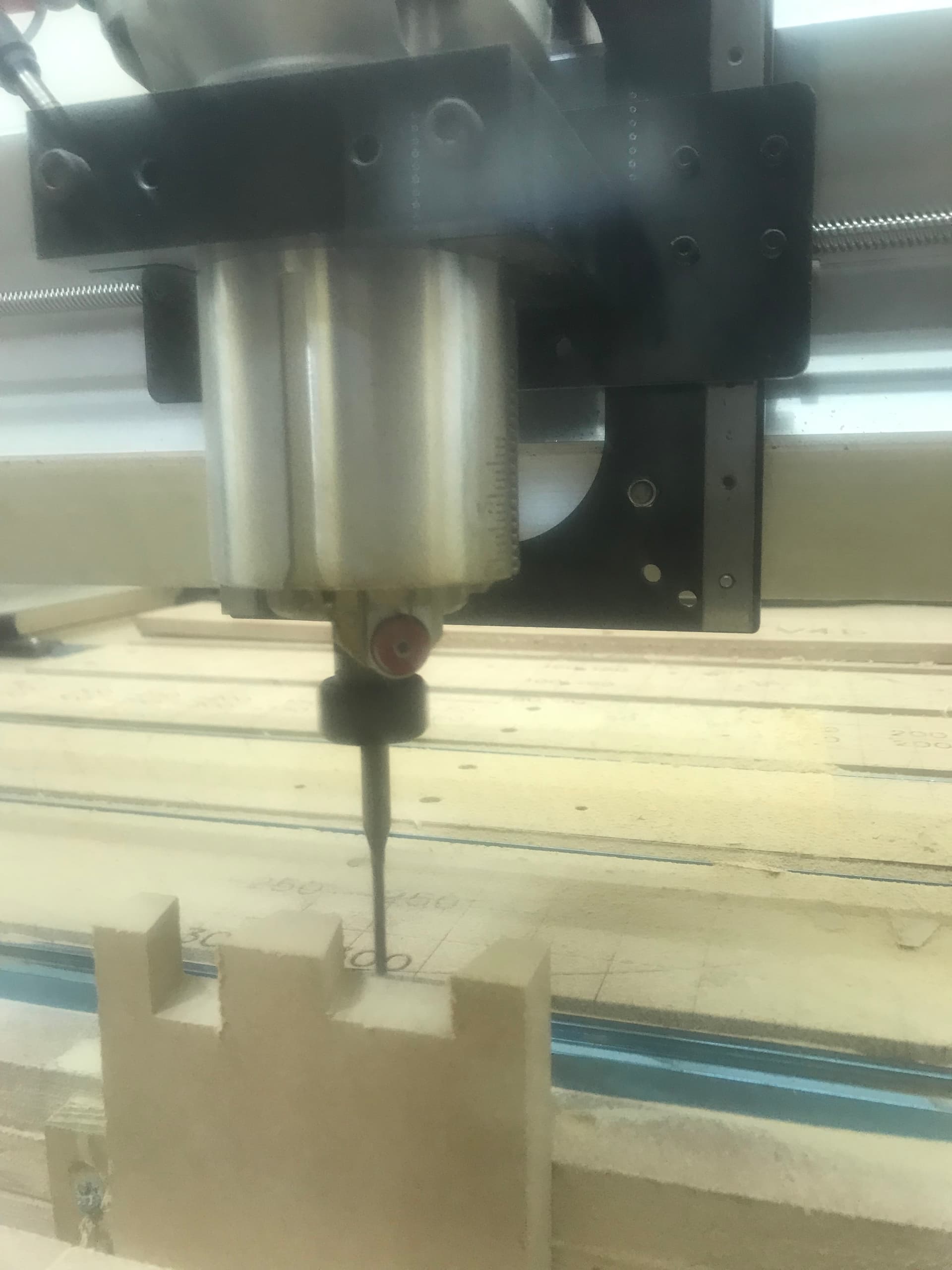
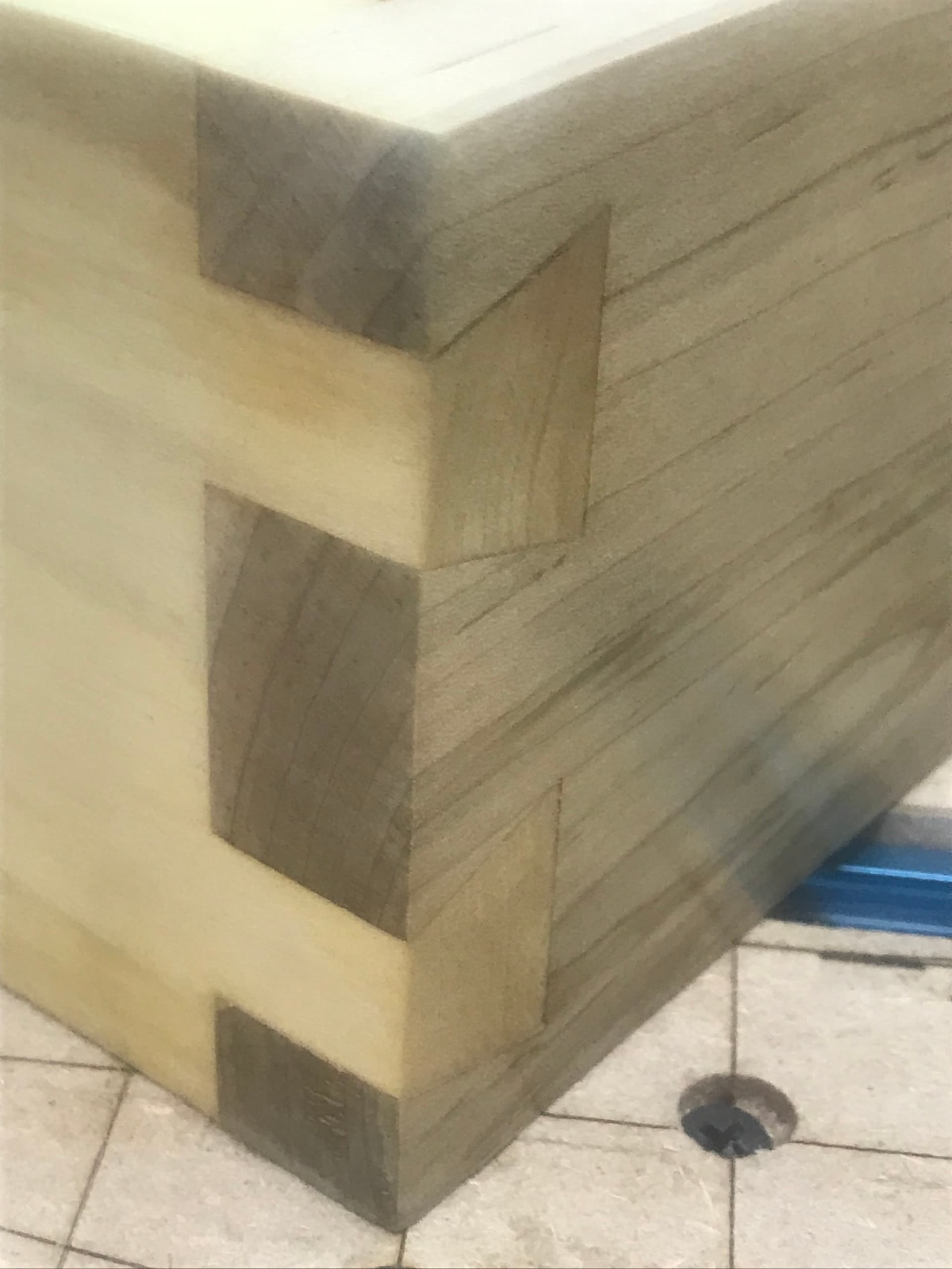
The pins is much better.
The tear out makes it look bad but the fit is tight.
So that’s how to make some dovetails on your CNC! If you have some time and patience you don’t need a Vectric Gadget or software beyond what you probably have if your a CNC’r.
The technique of just drawing a vector of where you want the bit to go and back, using the profile tool path at full depth can also be used for keyhole bits. Make some keyholes and T-tracks!
Thank you for the somewhat long read if your still hear! With a little luck and a lot of sanding you might make a joint that’s half decent!
Dovetail Guide.crv (788.5 KB)
_Michael
michaels-dovetail-guide-1.pdf (885.7 KB)