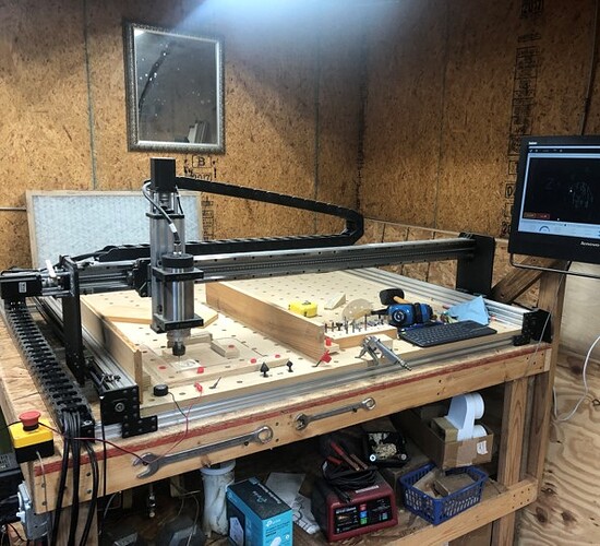
When I decided to get a CNC Machine I went with a Bulk Man 3D 1515 ULTIMATE Bee Full Kit. This is a 1.5M x 1.5 M (~48” x ~48”) Chinese import machine. The frame is built using 4080 C-Beam and some 2040 and 4040 extrusions for stiffening. Power is transmitted using 12 mm SFS Series Quiet Transmission Ball Screws. The X & Y axis are 10mm pitch and the Z axis is 4mm pitch. The gantries run on HGR Linear Rails. For my kit I selected the Spark Concepts xPRO V5 controller with High Torque NEMA 23 Stepper Motors. For a spindle I selected the 2.2 KW Air Cooled Spindle in 110V.
When I got everything assembled and running, I investigated GCode Senders. I did not like the various ones suggested by Spark Concepts, these were primarily CNCJS and UGS. I then found gSender. I love the interface and because the xPRO is (or WAS, more on this later) GRBL ESP32 it worked well for me.
As a technical person, I always want the latest firmware on my devices. Spark Concepts moved from GRBL ESP32 to FluidNC as a base for their firmware. I thought: “No problem it says it is backwards to GRBL, it should just work.” The first thing that broke was the ability to make changes to the configuration of the GRBL. Settings on FluidNC are kept in a config.yaml file, which is uploaded to the controller via a serial terminal and the controller rebooted – I had bad flashbacks to remotely updating and configuring Cisco Routers early in my career. The next thing that broke was gSender would not detect my probe. The LED on the xPRO would light to show a connection, but gSender would not. The “upgrade” to FluidNC also seemed to be one way – at least I could not find documentation on how to roll it back to GRBL ESP32.
The configuration issue was a pain, but not a game stopper. Editing the .yaml file and reuploading took extra work, but once done it was done. The probing was another story. Manually setting the workpiece zero is a pain. My eyesight is not the best anymore and lining up the tip of a V-Bit on an edge was a pain. And more than once I tapped GoTo instead of Zero on the Z Axis – this would generally drive the bit into the workpiece (I have mentioned this elsewhere in the forum. While not a total game stopper – the probing was less accurate and a major pain.
So, I bit the bullet and purchased a SuperLongBoard. I had already purchased a Touch Plate – the plates that came with my kit were kind of junky. One was like the Sienci Touch Plate – but low quality. The second was a Z only puck. Now that the SLB has arrived. I will need to start documenting the process of converting my rig.
The first hurdle was the power connector. The power connector on my xPRO is the same 5.08 pitch connector, but the polarity is reversed – positive on the left vs. right. No big deal, small screwdriver to the rescue. It would have been nice if the connector was included with the SLB.
The next hurdle was the stepper motor connectors. The xPRO uses 3.81mm pitch connectors and the SLB uses 5.08mm pitch connectors. Amazon and credit card reward points to the rescue – thank God (Jeff) for Prime Next Day delivery. Again, it would have been nice to have the connector with the SLB. Maybe an option in the ordering SLB to include the power and motor 5.08 connectors for those not upgrading from a LongBoard to a SuperLongBoard.
The next hurdle was with my limit switches. I have two wire basic mechanical limit switches with just wire ends, not molex type connectors so I must use the 3.81mm pitch connector. Not a problem, except I need three grounds – one for each axis. I have ferrules on my wires so I could not get all three into the one ground spot – two fit. I used the GD spot on the Spindle/VFD connector just to the left of the AUX Limits header – any ground in a storm…
Touch Plate and E-Stop were no problem.
I am using RS485 to connect to my Spindle/VFD. On the xPRO I have a twisted pair of wires with a resistor (100 ohm ¼ watt) between them on each end. Once I figured out which wire was the “A” and “B” I was able to connect the VFD to the SLB. I find it interesting that the link in the manual for the VFD settings is from Bulkman3D.com – which is where I bought my rig.
Time for Power On – gee those LEDs are bright, especially the CND Status. E-Stop and Probe act like they should.
Now to connect with gSender. Change the firmware to grblHAL. Select the COM port and I get an ERROR Opening Port COM… The SLB is not connecting via USB. It is not the cable, I installed gSender on my laptop and I was able to connect to the SLB with the 10-foot-long cable I was using with my xPRO. Windows gives me a “This device cannot start. (Code 10)” in the Device Manager. So, Ethernet to the rescue. Luckily, my PC has Wireless and Ethernet for connections. And speaking of networking. Something that would happen when my xPRO was powered up. It would knock out my ethernet connection on my PC when it was powered on. Apparently, I won’t have this issue with the SLB.
Now that I am connected, I have movement, homing and probing working. I had to reverse the X and Y axis, Z was fine. It seems a little rough, but I am assuming it is because the default settings in the SLB are for a LongMill and will need to be changed to match my gear.
Now, on to getting the settings set. I have run into issues with setting for the Firmware. I would set something and when I clicked apply, the setting would revert to whatever the default was. This was a pain. Updated gSender to 1.4.7 and problems seem to go away. (always update your software)
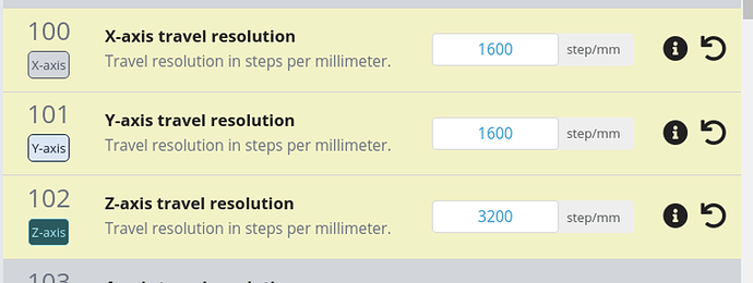
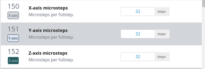
Migrating from the xPRO’s FluidNC config.yaml file to grbl type $## notation was not too difficult. The biggest pain is that the .yaml file the everything is grouped by axis and the grbl $## settings are grouped by function. All the steps/mm together, all the max rates together, accelerations together, etc. In other words, there was a lot of flipping between parts of the .yaml file while entering the settings in gSender.
The next stumbling block was the spindle. I could not get the SLB talking to my VFD. I checked and double checked all the settings in the VFD and SLB. I even posted to this forum: Huanyan v1 VFD via RS485. The next morning, I verified the settings again and to my surprise the spindle came to life. I looked at the .json files that are created by the export settings in gSender. The only difference between 5 pm July 1 and 9 am July 2 is the $30 and $31 settings were different. The July 2 file had quotes around the RPM setting and had trailing zeros. So, the working lines looked like: “$30”:”24000.000” vs. “$30”:24000 I don’t know why the setting changed, I did not change the setting. But the why and how doesn’t matter if it is working.
I ran a gcode file in the air without a tool and it now movement is very smooth. I did this before noon and it was already over 90 degrees F in the workshop. As it has been very warm here in Central Texas, I will have to wait for a cooler day (or early in the morning) to get back into the workshop and run a job for real.
Hope this is a help to someone else.
James W. McKeand


