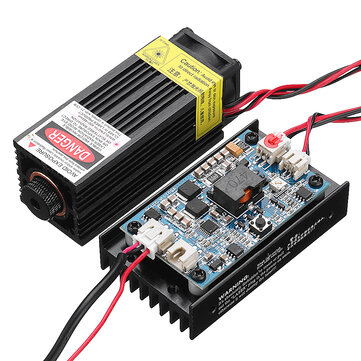
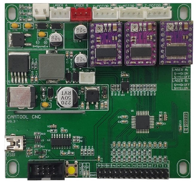
@gwilki, @paullarson, @stevendq, @lumpy, @alanbabb, @JHahn or anybody else using Banggood 5W laser. - Ok guys, my turn for some setup help. I have had my laser setup on the longmill since last year and it has worked perfectly, no problems. My grandsons will be spending most of summer with us so I decided to move the laser to an older 3018 (toy) cnc that I no longer use. The 3018 has a control board with the name Camtools CNC V3.3 that has a connector for a laser as well as a spindle. Well, the spindle quit working so I put the cnc away. Now, again, I am trying to get the laser working on the 3018 and having running/wiring issues. I originally had the 3018 12v power supply hooked up but found out that it was only capable of 1 amp output. So I switched to the 12v laser power supply that has 5 amps output. That solved my power issue. Now comes the fun part. I can’t get the PWM to work. It’s either off or on full power. I have searched the internet upside down and backwards and can’t find much in the way of help. I have uploaded a picture of the laser and the control board. I wired the + and - from the red socket to the + and - on the 3 pin socket on the laser board and get full power to the laser. But when I connect the PWM pin from the red socket to the PWM pin on the 3 pin laser controller board nothing happens. I still get full power. I even wired the red socket PWM pin to the 2 pin PWM pin on the laser controller board and grounded the other pin on the cnc controller board with no effect. Is there some need for a resister somewhere in the wiring? Also on the cnc controller board on the right near the middle is some silk screen printing that references turning on/off a S+ or S- switch or setting. I have no idea what that means. TIA for any help.
@Heyward43 I still have my original banggood, H. It looks the same as the one in your pic.
One quick thing. Did you turn on laser mode in grbl - $32=1.
I need to read your post a couple more times, since I’m slow, and I’ll come back here to likely ask more questions.
@gwilki - Hi Grant. Figured you’d be the first to respond. Yes, $32 is = 1. I’ve tried using the PWM on the 3 pin connector and the 2 pin connector but neither will reduce the power or turn it off.
I have had this issue with multiple laser modules. It has always been related to voltage leaking back through the ground. The grounds are tied together in the laser module. What I have done to solve this is use the ground on the longmill control, the one on the plug along with the PWM output, and run that to both ground inputs. Tie the PWM output from the longmill to the PWM input positive and then tie the power supply positive to the power input positive and do not use the power supply ground.
@Heyward43 I looked for any information on the CAMTool CNC board and couldn’t find any so I can’t provide any useful help. Sorry. Did you get any documentation with the board?
@paullarson - Same problem I had Paul. One would think it should be just straight forward and wire it like the board is laid out. But, no, it doesn’t work that way. Not any documentation really other than it’s GRBL 1.1f loaded.Thanks for responding though.
@alanbabb - Thanks for the info Alan. Only thing I see in your response is the mention of the longmill. This is to be mounted on the 3018 cnc controller board. I think I can try what you are saying though. I just have to think out in my mind which way to run the wires since the cnc control board only has 3 pins (+, - and PWM.
@Heyward43 Just to make sure that I understand your setup, H, are you using the laser’s 12v power supply to power both the laser and the 3018 board? Or, you are using the 3018 power supply for its board and the laser’s power supply for the laser?
Here is how mine is wired. In your pic, the white connector with the red blob (sorry to get so technical) is the laser power and the one beside it is the fan power. In my case, both of those go to the laser module - one set to the laser and one to the fan.
Now, this where we differ. On the three pin jack, I use only the + and - pins. I run power to them from the laser’s power supply. The third pin, labelled pwm/ttl on my board, I leave open. Then, on the two pin connector beside it, I run the + and - to the long mill controller spindle output. On my board, the two pin connector is labelled pwm/ttl + and -. I had to be careful with this one as the male connector that I had to fit into the female connector on the board fit sot that red was negative and black was positive - the opposite of normal. If they are reversed, pwm does not work.
Now, in your case, you would be running from that 2-pin jack on the laser control board to the 3018 board. However, that board has a 3-pin laser output. I’ve looked at a few websites and it would seem that you need to run from the middle pin and one of the end pins. I can’t quite see which of the outer pins, though. From the pics that I saw, the left pin in your pic is +, the middle is pwm, and the right is -. I would be inclined to try middle and right, but that is just a guess.
@Heyward43 Grant’s setup is the same one I use. The 2 pin connector goes to ground and PWM on the LM controller.
Sorry, i spaced on that point. Let me pull out my old 3018 and see if I can see how the laser was hooked up on it.
@gwilki, @paullarson, @stevendq, @lumpy, @alanbabb, @JHahn - I don’t know how to explain this guys BUT, I went to the 3018 and checked my wiring and found 2 wires reversed. Straightened them out and IT WORKS. I know damn well I tried the correct combination of the wiring over the last 4 days working on it but it wouldn’t work. Now it does. Thank all of you for trying to help. For further info to pass on I ended up using the 3 pin red connector on the cnc controller and plugged into the 3 pin connector on the laser controller. I did have to reorder the wires since the two connectors had different pin layouts. I even ran a short 2 inch x 3 inch test to make sure all was good. Thanks for all of your inputs again.
Grant, I originally tried using the 12v 1a cnc power supply but it wouldn’t provide enough amperage to the laser. So I plugged the 12v 5a power supply into the cnc board and it drives both the cnc controller and the laser just fine so far. I haven’t run it long enough yet to see if it overheats but when I do I will keep an eye on it. I don’t think the cnc motors draw that much current. I think I saw somewhere max 2 amps which is interesting since the cnc power supply only outputs 1 amp. I’m pretty sure I tried all of the wiring combinations I could think would work including using the 2 pin connector for PWM and the laser ps for the laser but couldn’t get it to work. Anyway it works now so done deal. Thanks again for your input.
@Heyward43 I’m glad that you got it working, H. Have fun with your grandchildren.