I’ve been using Kiri:Moto and CamLab for both of my CAM solutions for my Sienci Longmill. They both work great, although limited options. Are there any CAM softwares that instead of using a rectangular block for your stock, that you can use a custom designed blank instead. For instance, I was designing an electric guitar neck and if I use a regular rectangular piece of wood to start with, it takes like most of a day to machine out the part. But if I was to cut out a blank that only had minimal amount of material to remove, is there any way that I could design the blank in CAD and maybe some CAM software would let me import that as the stock instead of a normal rectangular piece of wood?
@gtrboy77 Can you describe a bit more in terms of what you are trying to do? I use VCarvePro, but the starting point is still a rectangular piece of material. There are ways of limiting the carving that you need to do within that piece, though.
If you have a graphic of your shape, maybe I can help.
What I mean is any design you have, add another 1/4" of material to all areas that will be cut. Then rough cut the material to this size on bandsaw, tablesaw, etc. That way the CNC won’t have to spend all day roughing out the material that you just removed. I want to be able to import this rough cut of material as my starting point instead of a rectangle block so that the CAM software will recognize this and generate a shorter G-code.
@gtrboy77 Understood. I’m not aware of any CAD/CAM program that will do that. They all start with a rectangular-dimensioned piece of material. However, you don’t need to mill it all, and in fact, there is no reason that you want to usually.
For example, if you start with a rectangle, then draw or import your graphic of the piece you are going to cut out, you only need to do any milling on that graphic. You don’t need to do anything at all with what will be waste. Maybe if you could post a pic of what you are going to do, I could be more clear.
Dean, Fusion 360 lets you create a design for what will be your stock piece and save it as a part. Then when you’ve designed your new part and go to Manufacturing to set up the milling, you can designate the part you saved as the stock. It’s great for saving material because you don’t turn useful material into chips, and it saves time because you don’t have to do a lot of useless milling just to get to the fun part. In your case you could rough cut the basic shape of the body and not have to cut everything.
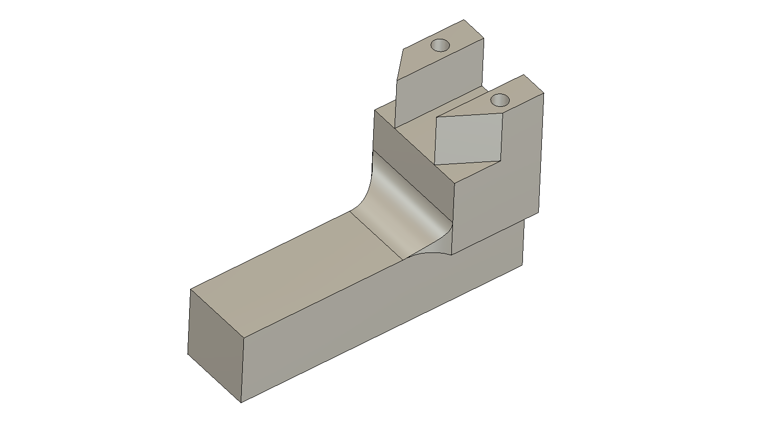
Here’s a part I designed for a ball turner for my lathe. It will be made on a 5-axis mill.
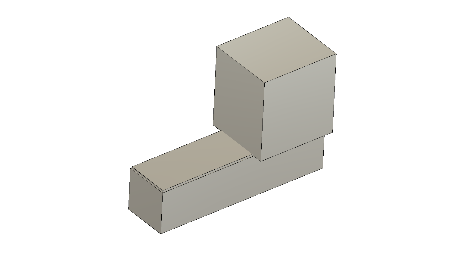
Here’s the part I’m using for the stock. Rather than start with a block of aluminum as big as the part, I can use a chunk pre-cut with a bandsaw. It’s bigger in all directions than the part I want, and saves a ton of time.
Have fun.
@BillKorn Tks, Bill. I stand corrected. Just for my education, where/how do you set the xy0? is it just a matter of choosing a corner and using that consistently through the design, then sender?
@gtrboy77 Sorry for the bad information, Dean. I would delete it, but I simply thrive on the embarrassment of being wrong. 
Grant, the advantage of the 5-axis is that you can set your Z axis any way you want, and then change it. I set it perpendicular to the face or region I want to mill. For the area in the part above, I make the face on the very top as the XY plane for that operation. Then to do the sides, I set Z perpendicular to each side. The controller seamlessly rotates the part in all 3 axes to position the part to face the right way. Fusion 360 has some neat multi-axis toolpaths that make organic curves and chamfers easy. And it includes shaft/collet collision avoidance, so it works out well. And it’s cool as hell to watch.
@BillKorn Are you using cncjs to send this to the Mill?
The mill has its own sender & controller, and it doesn’t use an Arduino, so switching will not be easy.
@BillKorn My bad. I thought that you were doing this on the Long Mill. Not so, yes?
That’s exactly what I was getting at. Thanks, Bill. That makes total sense.
You can definitely do this on fusion 360. If you check their tutorial video on double sided milling (where they mill one side from the stock, then flip the stock over and mill the other side) you will see them convert the piece, milled from the top side, into a mesh. Then use that mesh as the stock for the second side.
You just need to build the mesh, could use 360 or a modelling software like Blender.