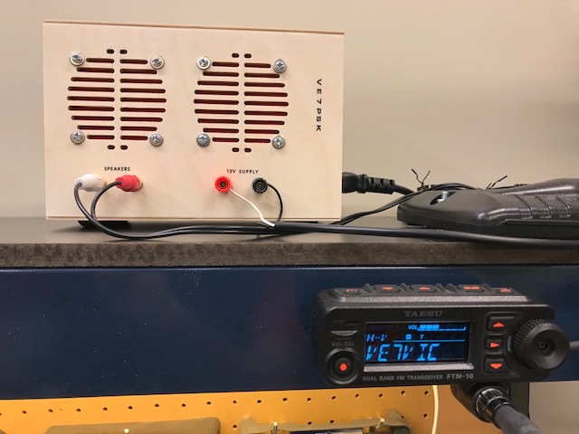
I decided to dust off my old amateur radio mobile transceiver, so I wanted to put together a 13.8V power supply to run it, ideally integrated with a couple of speakers so I could have better audio than the bitsy built-in speaker could provide.
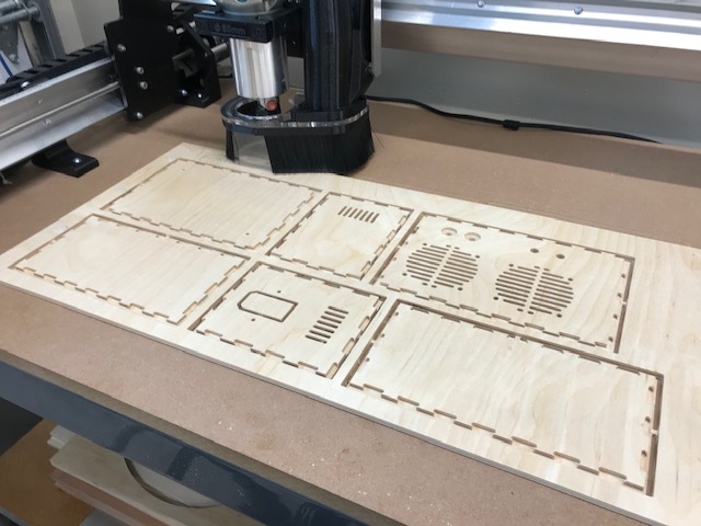
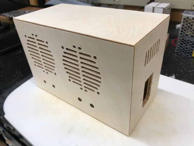
So I created this parametric finger-jointed box with all the necessary cutouts, and it went together great.
I just love being able to put together this kind of stuff in my own shop. Thanks Sienci!
Absolutely! As a former software developer (and someone who can’t draw worth a hoot) I use OpenSCAD to design most of my projects. I’ve attached the OpenSCAD source code for the power supply box.
Some tips:
In the code, the “cutouts” module determines what openings get cut in which panel (top, bottom etc.). Customize it to suit your needs.
The last line in the code is the call that generates the box. The last parameter in that call determines the view you’ll see in OpenSCAD. You’ll see it’s currently set to “machining”. Change that parameter to “assembled” to get an idea of what the assembled project will look like.
Be sure to set the material thickness and router bit diameter in the code where it says “Design parameters in mm”. I used 6mm baltic birch plywood for this because you can’t afford to have any voids with this level of detail. Measure the plywood with calipers and use the largest measurement for the code. There’s nothing worse than when the router almost completely cuts through the plywood.
I use Bosch 1/8" downcut bits with a 1/4" shank. They work great but they have ‘fangs’ (not sure what the technical term is) so if you zero the axis with the touch sensor they won’t quite cut down to the bottom of the material in the middle of the bit. For the Bosch bits I lower by bit by 0.55 mm and re-zero the z axis to ensure complete cut-through.
That’s all I can think of. If I can be of any help, please ask.
Freecad has an Addon called LCInterlocking which allows you to create finger jointed boxes etc. but I think all the finger joints are “through joints” thought.
Thanks! I’m actually quite fond of finger-jointing myself, but I object to seeing the dog-bones (or worse yet, skipping the dog-bones and having to file out all the rounded corners).
But you’ve given me an idea though: Maybe I could re-position the dog-bones to the bases of the fingers (rather than the sides as they currently are) and put a flange over just the dog-bones and leave the rest of the fingers exposed.
That is correct. I export the STL file and then use Kiri:Moto to generate the gcode (I tried CAMLab but it took one look at the STL file, had a seizure and produced a zero-length file).