Hey Everyone! I am brand new to CNC milling and I’m having an issue with either GSender or setting up my g-code in Fusion 360. What happens is when I use the Auto Zero touch plate, it zeroes perfectly. When looking at the project on GSender, it shows that the item is below the z-axis, but that is because I put my stock point on the top side of the stock in Fusion 360. When I do a Test Run, it will show the correct tool path, however, when I click the button to actually run the project, the z-axis plunges and starts traveling to the start point, but below the z-axis. This cuts lines completely through my stock. What am I missing here? I even set up the Safe Height to 20mm, but it still plunges, instead of raises, when traveling to the start point. Again, I’m using Fusion 360 and G-Sender with the AutoZero touch plate.
@pawiseman1 Welcome to the group. I’ve moved your topic to the Fusion360 category. I believe that this has come up before wrt fusion360 users, so it may get more traction here.
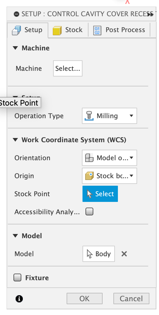
@pawiseman1 it sounds like the Z zero in Fusion is not the same as the Z zero set in gSender.
In fusion, when you set up your stock, you can move the origin to a point on your stock box - this needs to be identical to the zero point you are probing for in gSender.
That means you set the Z zero either:
to the top of the stock in Fusion
by probing Z at the top of the stock in gSender
or
to the bottom of the stock in Fusion
by probing Z at the waste board in gSender
Personally I prefer the second combination because it saves my wasteboard.
First of all, thanks for the replies! I’m going to include some photos and code to show exactly what I’m doing here. @elbarsal I believe I am setting up the stock point and the auto-zero to the correct position. I’m including pictures to show you exactly what I’m doing, but with my limited knowledge…it may make sense to be, but be incorrect. And thanks for the tip about the wasteboard! @NeilFerreri I’m including the first few lines of the g-code below. It always happens at the very beginning of the process. When I hit my Oh No! button, it always stops within the first 30-ish lines of code…so it has to be happening there, right? So I’ve copied my code a bit beyond 30 lines.
This particular project I’m sharing is for a control cavity recess for an electric guitar, so I can fit a control cavity cover in flush with the back of the guitar. This code is for 2D adaptive clearing (as everything I’m working on right now is a template on 1/4" plywood, but I do measure the thickness of the plywood and enter that for my stock thickness instead of defaulting to 12.7mm…also, I do everything in millimeters). Most of the templates I’m working on (that have this same z-axis issues) are 2D Contour programs. So, to be succinct, I have this exact same problem with 2D Adaptive Clearing and 2D Contour.
Thanks again!
G-Code:
(Control Cavity Cover Recess Template G Code)
(T4 D=6.25 CR=0 - ZMIN=-12.7 - flat end mill)
G90 G94
G17
G21
(When using Fusion 360 for Personal Use, the feedrate of)
(rapid moves is reduced to match the feedrate of cutting)
(moves, which can increase machining time. Unrestricted rapid)
(moves are available with a Fusion 360 Subscription.)
G28 G91 Z0
G90
I started the photos here, but as a new user, I can only upload 1 at a time…so I just made a Google Slides presentation with the images I promised in the earlier post.
The last photo is my actual machine, with the actual stock I was using to run the program I shared the g-code for in my earlier post. You can see the machine has plunged into my stock, my spoil board, and potentially my cnc tabletop. You can also see the remnants of a previous project that cut into the spoil board while traveling to its start point in one of my 2D Contour projects.
I hope all this helps you guys to be able to see what I may be missing! Thank you again for your willingness to help!
I think so? I know where it’s located on the screen and I know I’ve clicked on it to see the options, but I’ve never toggled it. Is the G56 because I have the WCS offset in Fusion 360 set to 3? When I get home tonight, I’ll work on uploading a screenshot of gSender with this program loaded.
If so, there’s no particular reason I’m using it…I just followed along with a guy on YouTube to design the 3D model of the whole guitar…and that’s how he set up his projects. I honestly had no clue what I was doing…ha ha. Just doing something to get my feet wet and learn CNC and 3D modeling.
Yes. By default, you’re using g54. So when you set your Z-zero, you’re setting it for an entirely different plane. Then you switch to G56 when you start cutting and who knows where zero is there.
Anyway, if you’re just doing that one cut and you are resetting your zeroes for each job, just use WCS 1 (G54)
I edited the program where the only thing I changed was the WCS Offset to 1 in Fusion 360. I was on the G54 (P1) plane in gSender, however, the router still plunges. I used the AutoZero touchplate first, then I just tested setting all the zeroes manually and got the same result. At least I know that there is not an issue with my AutoZero touchplate! I am including the first 30, or so, lines of update code for this project.
I am including a video that shows the program running with the Oh No! Button on…that way you can see the path it’s trying to travel without the noise and without destroying my table and spoilboard. You can see it dip…and this happens in the first 15-30 lines of code. I made sure to get a video of everything on my screen so you can see my settings, and then a pan over to my router so you can see how it’s trying to plunge into the spoilboard/table. I was wondering if there was a mm/in error, but when it travels to its start point, it works perfectly…it’s just traveling below the z-axis instead of above it. So I don’t think there’s an error with differentiating between millimeters and inches (I use mm on my projects).
Link to video:
G-Code:
(Contorl Cover Recess)
(T4 D=6.25 CR=0 - ZMIN=-12.22 - flat end mill)
G90 G94
G17
G21
(When using Fusion 360 for Personal Use, the feedrate of)
(rapid moves is reduced to match the feedrate of cutting)
(moves, which can increase machining time. Unrestricted rapid)
(moves are available with a Fusion 360 Subscription.)
G28 G91 Z0
G90
Do you have a G28 set?
If not, replace this line G28 G91 Z0
with G53 G0 Z-5
What post processor are you using?
Explanation: G28 G91 Z0 // This line moves the Z-axis to wherever you have set G28 (I’m guessing you have not set it intentionally)
The intent is that G28 will be at some safe height ABOVE your work.
G53 G0 Z-5 // This line will lift, rapidly, your Z axis to 5 units (mm in your case) below your limit switch…you could change that 5 to whatever you want
That changes things. Just delete the g28 line and make sure you’re Z is clear of any clamps and stuff. It’s tough to do something like a guitar without switches. The limit switches are the only absolute reference point on the machine.
You definitely don’t want to use G28 or G53.
Deleting the G28 lines at the beginning and end of my gCode worked perfectly. This solved my problem! Thank you @NeilFerreri , you are a life saver!
To anyone reading this thread that is having the same issues I had, and you are new to this, let me just share with you the way @NeilFerreri suggested I solve this problem…
When you are done creating your cuts, and you are happy with them in Fusion 360, go ahead and click the button to generate your code. When you are on the screen to post the code, look on the left hand side, under the name of the project, and at the bottom you’ll see a check box that says ‘Open NC file in Editor’. Make sure that box is checked and when the code is posted, you’ll get a text box with your code in it. In my case there was a line at the top that reads: G28 G91 Z0 …delete that entire line.
Scroll down to the bottom of your code and delete the G28 code line there, too. In my case it read:
M9 G28 G91 Z0
G90 G28 G91 X0 Y0
G90
M5
M30
Delete both of the G28 lines, or it will continue to send your router through your project at the very end of the project.
To be clear, the reason this is happening, and @NeilFerreri , please correct me if I’m wrong, is because I do not have limit switches installed on my machine. If I had them, I assume the G28 code would be fine to leave in. Again, if you do not have limit switches installed on your machine…DELETE THE G28 LINES IN YOUR GCODE and your project should work just fine!
@pawiseman1 I’m glad that worked, but this should just be taken care of with your post processor. What post processor are you using? Most I’ve seen have G28 as an optional checkbox. You could modify the post processor to leave that unchecked by default.