I almost have my Longmill setup and have some questions about Y track alignment.
Measuring parallel spacing, the tracks show no more than 1MM difference from back to front: 3 of 4 measurement are bang on and only last one (front) shows 1MM difference.
Measuring diagonally, I see about a 1MM difference.
Distance of Y gantry mount plate from back of plate to X point are bang on both sides.
Are these tiny differences anything to be concerned about?
Moving the X gantry along the Y axis from back to front shows smooth movement however when returning Y to zero, I hear some groaning noise coming from the left Y track (from the front perspective). The noise begins over the first Y support leg, recedes and returns over the 2nd support leg and continues until the X gantry stops at the back.
I’ve tried adjusting the v-wheels:
left v-wheel is tight and won’t turn by hand - eccentric nut is turned for max looseness;
right v-wheel seems just about right - I tried tightening but it has no effect on left v-wheel but I have a little more room to tighen here.
Bottom v-wheels seem just about right with ability turn by hand.
Should I be concerned about the groaning noise since X gantry does move forward smoothly and without noise? Note that backwards movement appears to be smooth as well, but for the groaning noise.
Setting Y track alignment has been most difficult part of setup and getting excited to lock it down and spin 'er up.
Y axis rails are now bang on in terms of parallel distance at 4 points.
Diagonal measure is off by 1/16". Tape measure isn’t ideal measuring tool but I believe 1/16" is correct.
I realized that continuous jog of the X gantry does not produce groaning noise; I only get the noise when returning Y to Zero which moves faster than continuous jog.
Front Y v-wheels don’t sit perfectly on the rail. Both sit a little outside the rail - 0.5-.75MM. Rear v-wheels are fine.
X rail isn’t perfectly square to the grantry supports which probably explains the previous point and I’m not sure if there’s anything I can do about it. I’m also not sure it matters that much. If XZ is always in the same place and starting point is correct on the piece to be milled it should not matter, right?
Getting v-wheels to right tension seems near impossible. Some are good and some barely turn by hand but they do turn. Still tweaking.
I tried loosening the backlash nut on the left side to solve the groaning noise and jogging seemed to work fine but Returning Y to zero produced a sudden skew on the left as if the support ran into an obstruction and X went completely out of alignment. I assumed I’d loosened the backlash nut too much so tigtened it and that hasn’t happened since but will run it a number of times before I feel certain.
Now I just have to level the spoilboard so height is consistent at all points along Y. I have X level within 0.5MM but Y still needs work. I’m almost there.
I’m beginning to realize that marrying a CNC to a wooden table can’t deliver perfect alignments. If I had to do it over, I would have taken a little more care to ensure the 2x4 frame was flatter but getting 2x4’s to remain straight is near impossible. I thought I did a good job with the frame but I didn’t know how exacting the Longmill would be.
So I am tweaking and tweaking and tweaking and may have to accept the groaning noise and v-wheel misalignment.
Feedback and/or insights are appreciated. I’m a total newbie to this and figuring it out as I go.
@glenn Can you describe more about some of the V wheels sitting “outside the rail”. That does not sound right. Pics would be good, too.
The X gantry should be square to the supports.
Have you done a calibration in gSender? If not, you may want to do one. That way, you will know with a great deal of accuracy if you are out of square. You’re right; at tape measure is not ideal for this.
If your table is not out too much, surfacing the spoil board will be enough. If it is out a lot, though, you may want to work on the table itself. If you used construction 2 x 4’s, it’s tough.
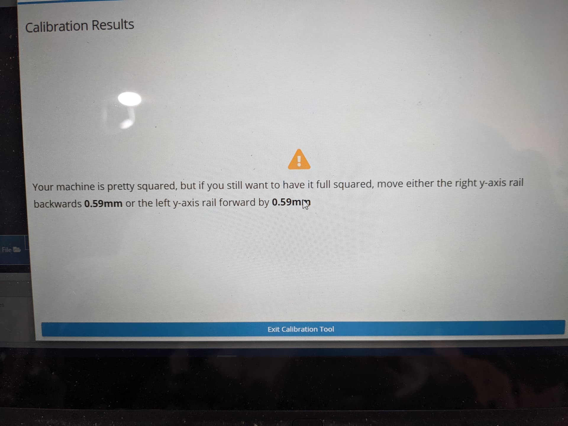
Thanks for getting back to me on this. I ran the calibration and it came out pretty good. See attached photo along with photo of v-wheel. Left is a hair worse than right and left starts out aligned and moves out towards the front.
I’m not going to move the Y rails to get calibration perfect. Moving one of them by .59MM won’t work because the existing screw holes will just pull it back to it’s previous position. I’ll save that for V2 of the table.
I noticed today that my Y gantries went out of alignment again. The left was trailing the right by a little.
Would that mean backlash screw is too tight or loose? Does screwing in tighten or loosen? I assume it tighens its hold on the threaded rod but I could be wrong. I’m going to run Y back and forth and see if it goes out again.
Also, is there a way to spin one Y alone? So far, I’ve just run it to the back to realign them which I recall reading in your instructions but I don’t really like doing that. It sounds damaging.
@glenn Tightening the screw tightens the anti-backlash nut. I suggest that you back them both off all the way, then tighten them only enough to eliminate all movement back and forth. It may be a good idea to loosen the bolts that hold them to the gantry and run the machine back and forth, then tighten them again.
There is no way, short of turning the lead screws by hand, to move one and not the other. You will not damage the Mill by running them both all the way to the back or front. I do that before almost every job to ensure that my Mill has not lost a step or two.
Another thing to check is the wiring on the motors. Make sure that they are both firmly plugged in. If this has always been an issue, you may want to verify that all the dip switches are set as they are supposed to be. Even if they look good, it’s worth moving them back and forth to ensure they are all the way where they should be.
Glenn, as a very experienced woodworker myself, I’d like to make a suggestion regarding the following comment you’d made in your previous post:
“I’m not going to move the Y rails to get calibration perfect. Moving one of them by .59MM won’t work because the existing screw holes will just pull it back to it’s previous position. I’ll save that for V2 of the table.”
What you could do is remove the screws and plug their holes with a piece of hardwood (which you could make yourself) sized a bit bigger and slightly taller than the hole. I’d recommend you glue in the plug, then once you’ve given the glue a while to set, trim off any excess. This plug should enable you to place a new screw into its new location with very little likelihood of it following the previous screw’s path.
Oh, and for the record, I’ve also experienced the same V-wheel misalignment issue. I believe mine is a result of the slightly misaligned brackets on the end of the X-axis, caused by the stamped steel angle iron pieces. Although I’ve shimmed them to bring them into correct alignment, they’re still out by a bit. Jeesh!
@glenn Further to what Marty has said, if you are going to be changing your Mill anyway, there is another solution. I have the feet holding my Y gantries on “slats” of MDF. The slats themselves are mounted to the table using 1/4" bolts that go through the slats and the table top. The holes in the slats are actually slots, not 1/4" holes. When I was first squaring everything, I snugged the bolts up, checked for square, and nudged the slats until the Mill was square. Then, I simply tightened the bolts.
I hasten to add that this was not my original idea. Someone on this forum proposed it and I stole it.
Thanks gwilki and Marty for the feedback. I’m going to try out Marty’s idea of filling existing screw holes and I like the idea of mounting the Y axis feet on MDF slats. I actually did that on this build but I screwed them in so they’re not movable unfortunately. I may just buy a new sheet of 3/4" MDF and build a new top. I used 5/8" originally to save a little money and while it appears quite rigid, i notice that it can bow slightly.
The v-wheel misalignment might be trickier to solve but I’ll look into shimming.
I redid the table top and it’s much better. Putting Y rails on an adjustable platform made a big difference and allowed me to adjust as needed. Calibration showed it was off by only 0.11mm (compared to 0.59mm previously). The outage was so small I doubt I can move it less than a hair width without making it worse so I left it as is.
The only issue I had was with the v-wheels. The x-axis plates are not square to the rail so v-wheels would not seat properly and would ride up and inwards by about 1mm. I can’t think of anything that would fix that so I put an additional washer on each rear wheel and this fixed that problem. Technically, this means X and Y and misaligned however if it’s a static discrepancy and Zero is Zero, then cuts should be fine…I think.
Something else I discovered which was a little shocking was that rear v-wheels were a touch too low and would actually contact the Y rail feet which would cause a tiny hop as they rode over on the left side! I would have expected the Longmill to be designed to ensure there would be sufficient clearance no matter how low the wheels sit.
Thanks for your help and feedback and any further insights are always appreciated. I have no idea what I’m doing and basically at the starting line with CNC and related tech.
Glenn,
I had the same issue as you with the rear V-wheels contacting the Y-rail feet. My solution was to remove a bit from the tops of those feet with a chisel. I assumed it was a screwup on the printing process… but no bigee to correct myself.

