Gotcha. I just put a couple of those spare bolts and lock nuts in place of it for now, until I get the drag chain myself.
1 Like
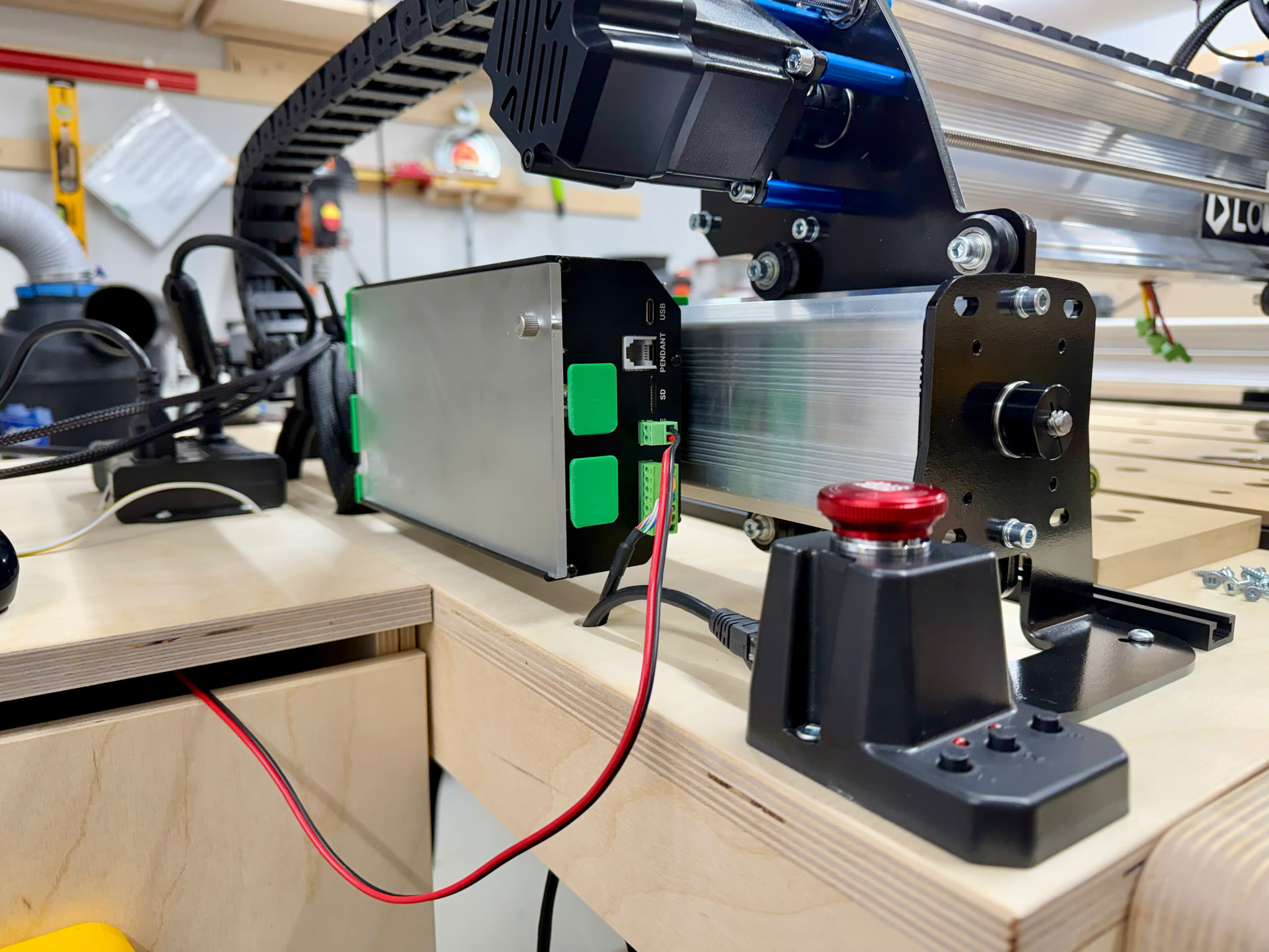
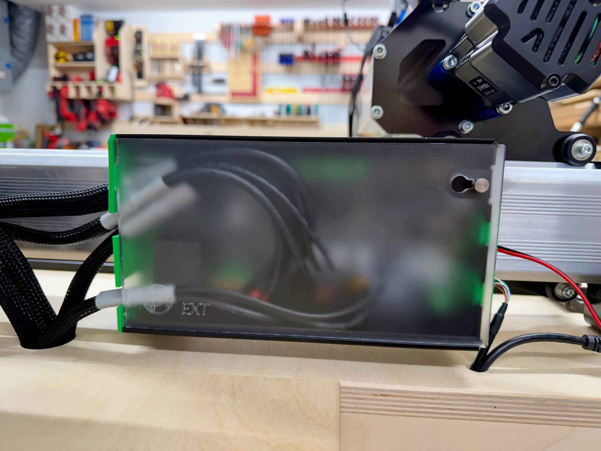
Am part way through installation of the CLSM kit. Instructions/pictures are not great. Instructions say to install cables from the R side of the enclosure, and cover plate is upside down, as indicated by others. One of the Sienci pictures shows cables from L side, just as dfrechette’s above. Confusing - have written to Sienci and await response.
Hi @Retiree,
I fixed the orientation to match my needs, but regardless, the larger cables must come through the larger openings. Once inside, the sockets are well labeled. You shouldn’t have a problem connecting each wire to the right one.
Regards,
Thanks for comment. I was following (blindly) the instructions and have run into a problem in feeding the cables through the cutouts on the R side - 2 do not fit into a cutout. Did not even think to look at the cutouts on the L side. As you indicate, they are larger, so should solve the issue.
For all the reasons you indicate, the board must be flipped to the “right side up”. I notice the end plates are screwed into the body of the container. Do not know how PC board is attached. Anyone try to undo the end plate bolts and flip it all the correct way? I do not have access to a 3D pointer to make new holding clips, which should be the correct solution, IMO.
Hi again @Retiree ,
I tried that at first – attempting to flip the circuit board – but it won’t work because you won’t have an anchor point for the screws at the bottom of the faceplates.
Regards,
Hate say it but this is very disappointing to see that Sienci Labs packaged up this Kit, and it’s seeming like a hack. Did anyone from Sienci say they would address this in the future?
1 Like
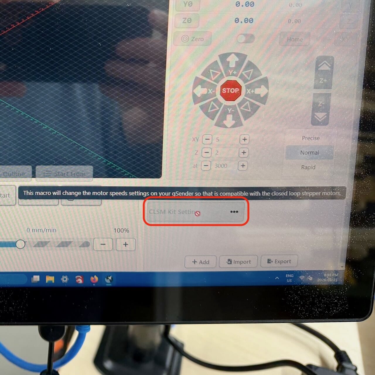
I have everything hooked up, but I’m unable to get the macro identified in the “Software Changes” section to run in gSender. Also, the “Motors” section shown in the instructions is not visible (this could be caused by the macro not running, preventing the motors from being recognized). I’m running the latest version of gSender 1.5.7 on a gControl. Has anyone else encountered the same problem?
I am still waiting for Sienci response to my basic wiring/installation issues, so have not got to the S/W changes yet. Disconcerting to hear you are having issues. At this point in time, I would not recommend buying the CLSM Upgrade Kit. Sienci must thoroughly test and document all aspects of this kit before putting it on sale.
1 Like
I got everything running. The instructions aren’t clear about what needs to be done before connecting the machine to gSender. Here’s what’s missing:
-
Make sure gSender isn’t connected to the SLB-EXT.
-
Before turning on the SLB-EXT, ensure the E-Stop is pressed.
-
Turn on the SLB-EXT and wait a few seconds for it to come online. You’ll see a red indicator light, and the motors will start making a hissing sound (this was unexpected).
-
Turn the E-Stop to unlock it.
-
Connect to the SLB-EXT in gSender. The light will turn white/blue.
Once you’ve completed these steps successfully, download the macro shown in the instructions and load it into gSender as shown. It should turn green, indicating it’s running.
After that, you’re good to go.
By the way, I reduced the x/y/z-axis acceleration from 1500 to 750 as shown in the screenshot in the instructions. I don’t want to overstress the machine during router movement (what they call “motion planning”).
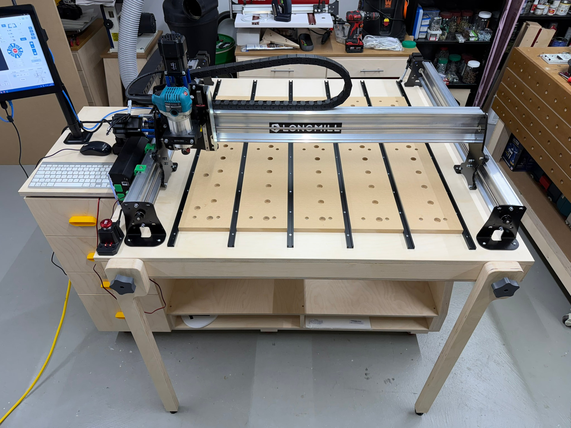
Oh, and before I forget – I was initially unsure how long the wide drag chain should be. I experimented and ended up removing 4 links from the total length. My machine is the 30 x 30 model.
Hope this helps.
Regards,
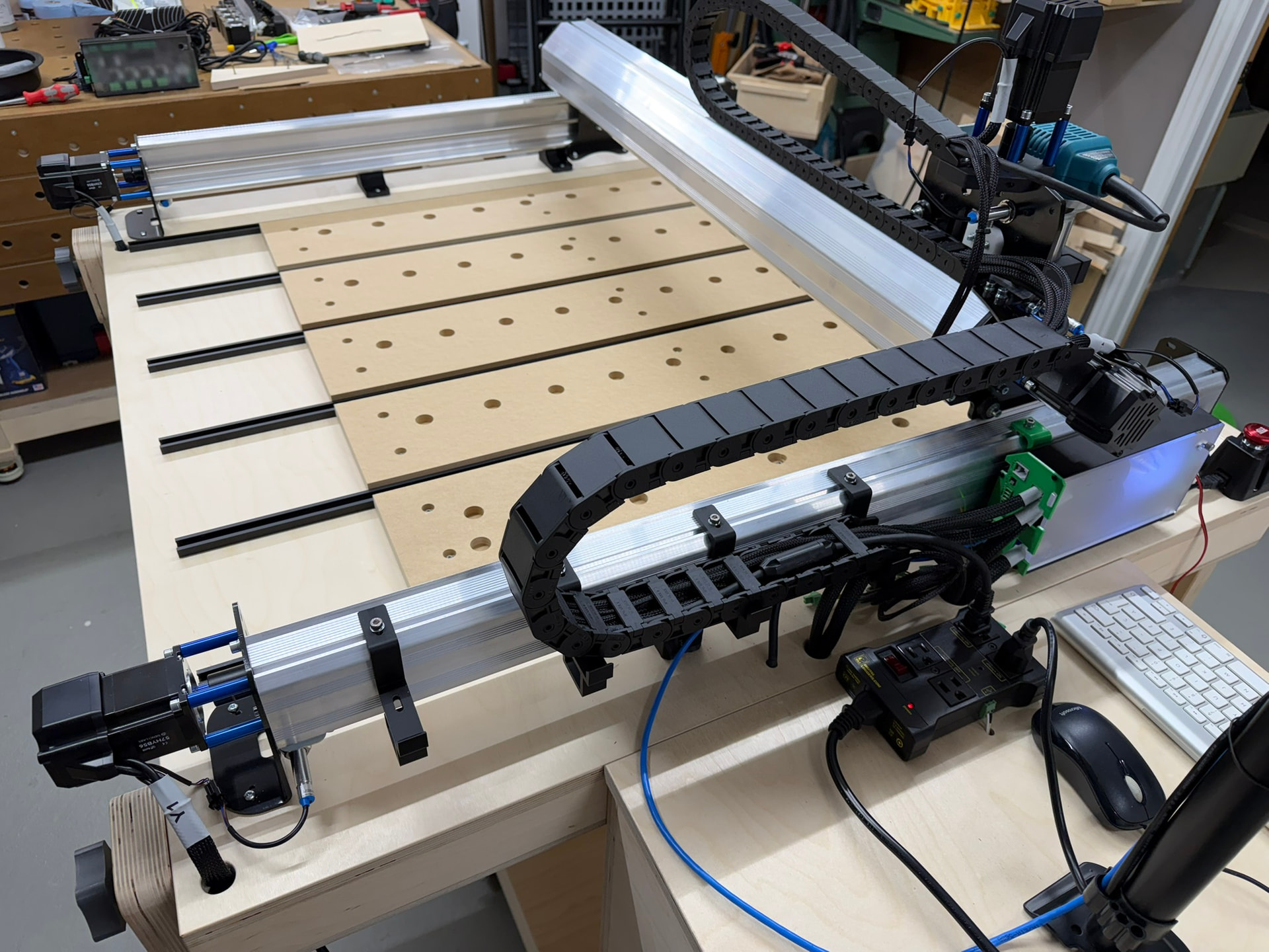
(Note: the extra cables you may notice are for the laser unit)
3 Likes
Thanks for sharing **dfrechette!
I’ve got a 30x30 as well and this could become invaluable! your steps will be memorialized (book marked for me).. I do wonder if I could get by without all the extra re-configuration of the SLB ends?If un-avoidable, I’ll farm out the print since I’ve since sold my 3d printer ¯\_(ツ)_/¯ .**
Hi all
I took the plunge as well — the CLSM kit and the Canadian-version spindle are on order. Really looking forward to it! Fingers crossed the installation goes smoothly ![]() .
.
1 Like
Update for my issues just received. Sienci response + my comments: “The orientation of the board is there by design because of the way of the cable management. If you haven’t reviewed the documentation recently they updated it with proper and less confusing images”. @R - do not understand “orientation by design”, but perhaps I do not have to. Still agree with dfrechette comments on “correct” orientation. Instructions STILL say to use R side for cable insertion. This is WRONG. The cables do not fit.
”The cables can be run in either side of the controller”. @R - no they can’t. They will only fit in the L side with the larger cutouts. Poor Documentation…again.
“The endplates are not symmetrical, reversing the board in the housing isn’t possible.” @R - good to know. dfrechette has confirmed.
Am not impressed to put it mildly. Will proceed with flipping cables to L side. Then will have S/W to go. Will provide update later.
1 Like
Thanks for the update… By chance do they post the instructions on line?
Installation instructions on Sienci website: https://resources.sienci.com/view/lmk2-closed-loop-steppers-2/
I have been trying to follow them diligently…
More Q’s re the inductive sensors (this is the first time I have installed)- for them to operate properly on the Y axes, what is approximate distance between the sensor head and the wheel nut? Also, the pic’s seem to show the Y axes sensors mounted against the back plate. Any clearance required or are they supposed to be butted against back plates?
1 Like
Another installation suggestion for newbies (like me). The new cable ends have a “sleeve” at the SLB end, and the sleeve has a protruding ring. The cables should be installed with the ring INside the SLB cutout to prevent any strain on the connectors. Dfrechette shows this in his pic’s, but I thought I would mention it.
1 Like
Super helpful, thanks!
Once I get my funding in order I’ll place an order, but I’m also thinking of replacing my Mikita with a spindle and I need to go into a 20 amp circuit. This upgrade probably needs to go first ¯\_(ツ)_/¯ .
Hi @Retiree, you need about 1 to 1.5 mm of distance between the limit switch head and the wheel nut. They must never touch.
Regards,
Appreciate the helpful info. Sure beats “experimenting”.
1 Like
Update. H/W installed and connected. S/W updated, including changes and process indicated by dfrechette (thank you!!). Not all smooth, but I got there. Turned it all on and tried Homing for the first time - Alarm Code 8. Tried the suggestions to address - no luck. Issue currently with tech support.
I did speak with tech support re the incomplete and erroneous documentation for this upgrade and offered to go through the documentation with a Sienci person, step-by-step, to help them improve. They do not have the time.
1 Like