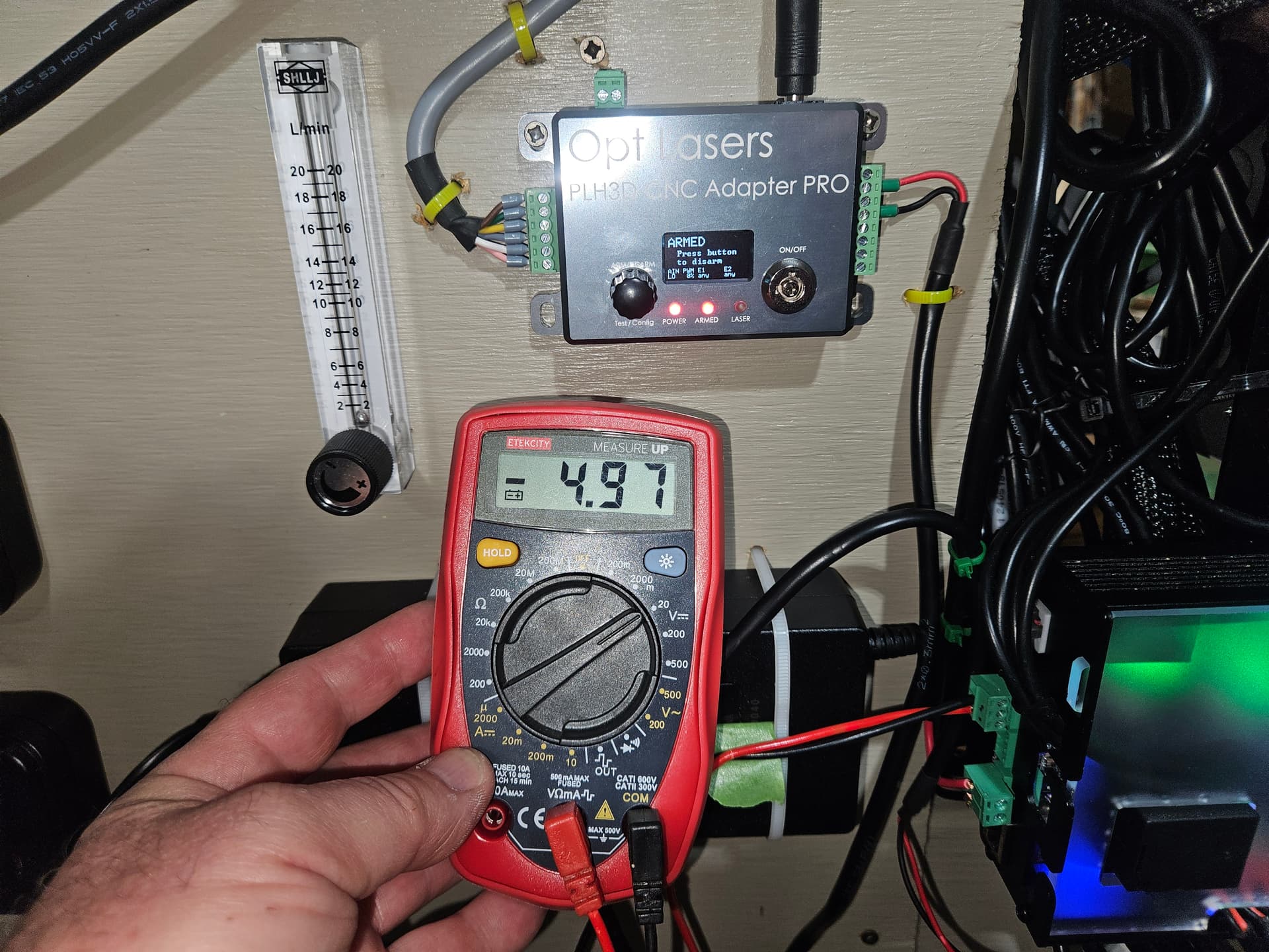
The output from the black and red wires from the laser connector on the SLB does not change with Laser ON and the slider for % power is increased. The active icon is changed to red. Voltage is 0.00 when off but -4.97 when turned on, regardless of whether the slider is at 20 or 80%. Bottom 2 connections are used with red on bottom and black at center of 3 wire connector. How can this be fixed?
@thankjun I’m assuming that you followed all the suggestions from your previous topic to set everything up, and that you have correctly set the drop down menu and the laser/spindle slider.
How are you measuring the output voltage? The values should never be negative, so that is one thing to address.
Exactly as Chris’ video showed in the technical manual. I am really thinking my board maybe shot. Yesterday I could not even run a simple file to drill 3 holes. Alarm 10 would not clear even though the red light was cleared on the SLB and gSender showed connected. Reboot finally cleared that then position was lost multiple times from center of board, Soft alarms until I disabled them in firmware, then Hard alarms and Alarm 14 took 6-10 tries to clear. I loaded previous firmware settings and then the default setting but still problems persisted. No contact from Sienci yet but I’ve sent daily updates now since Friday.
Also Y axis calibration changed by 20% and firmware settings gave error 3 when I selected H-100 for spindle
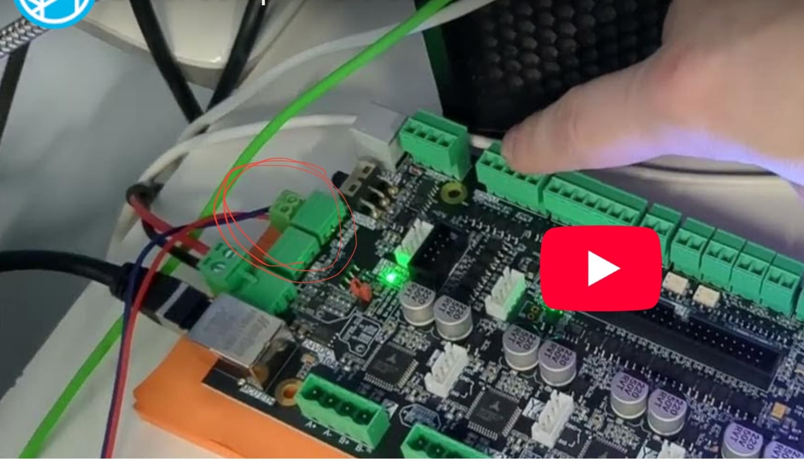
I was looking at your phote and had a wait.. what.. feeling when I looked at tne wiring of the laser to the slb. If I remember correctly, gnd was on the bottom side of the connector.
I did some lookingminto it and found the instruction video, showing the wiring you have but when I looked at the laserbeam instructions, I encountered this:
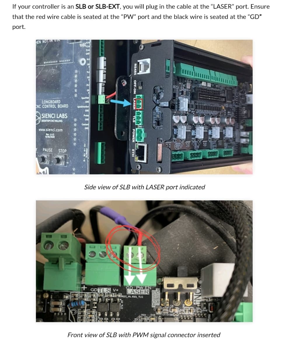
The silk screen on the pcba at the laser connector clearly stating ground being on the left (outside). And ground can be many a things but it will never be a red wire. When you measure between your red and black, you will measure a negative voltage, as you do.
So as an extra check, I checked the boards designations at github. Well, that is messing things up even more.
I still think that the silk screen on the board is the true setup to follow, leaving me stumped at how or why the video shows something that should not work.
Any input here @chrismakesstuff
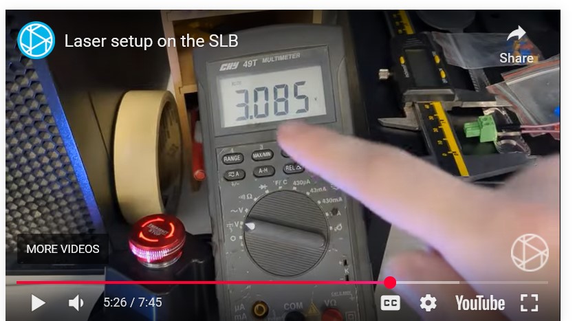
@thankjun I don’t know what video you referring to, but here is a screen cap from Chris’ video. Note the value is + not -.
Further, as per @Spamming_Eddie the pics clearly show that black is on the end and red is in the centre. By your description, you have that backwards.
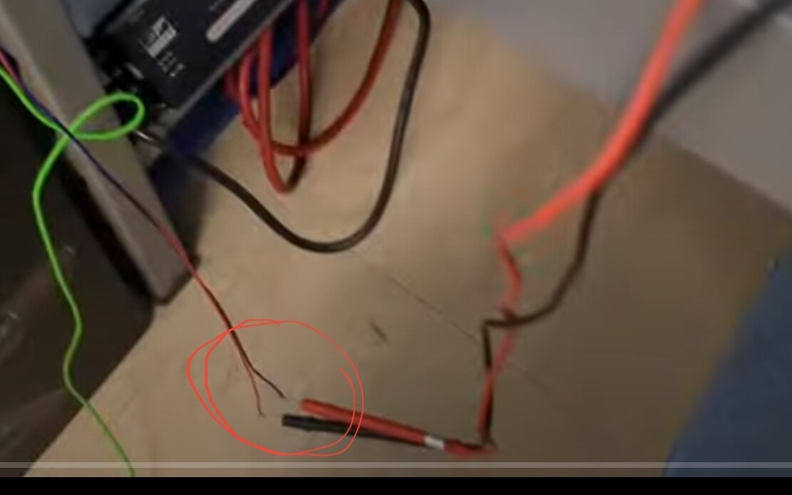
The refered video is found here:
Showing the weird config of the wires,
Addition:
I watched a bit of the video. Chris explains he has no laser plugged in, just a multimeter. When he pans over to the meter at 36secs into the vid, I was able to capture that the black gets connected to the red wire of the multimeter and the red to the gnd input.
Chris cheated!![]()
I had the black and red wires reversed until i was referred to the technical manual as I thought that was the way I had seen it. But when I searched Laser wiring again I couldnt find it. Certainly instructions should be easier to find and clear.
But the slider still isn’t working as I would expect values would change but be negative. Values didn’t change on mine.
I sure hope i can get info from Sienci soon.
I will test with wires switched when I’m able to get back to my Altmill.
Switched the wires and the laser fires. ![]()
THANKS for solving this!!!