@andy
I am completely overjoyed that you chimed in, so.
Your candid handling of this issue is the stuff of dreams… indeed, you are busy at the top.
I made the request because of the feeling I got in your videos… other outfits have never responded in that fashion at your level… I was not expecting much… After all I am but one noob in the billions. I also thought, my request was not needed, as you may have come in this thread without it.
What is interesting, is that every bit of what you say I have already uncovered in the last couple of days as I was digesting all the suggestions given in this thread. Thus I need not mention any one item, you covered it all!
To answer your request, indeed I will post my success/failure once I do put that temporary solution in place. …and yes, as far as I know now, with the MK2 as base.
…your response confirms I am thinking in the right direction.
So far, in the last few days, I have run into so many obstacles, and difficulties, I had to back off and digest the stuff before gnawing at it again. I took a small break! Yet I continued to watch videos and potential solutions, generally.
The main obstacle is in the software and hardware meshing, as you well know and mentioned.
I could already post a partial expose of what I have run into, but I will wait till I can produce a more complete write-up, and avoid a chain of small replies that get lost in the thread.
My appreciation for your write-up is without word. Thank you, so much!, Andy, Sir.
Thanks Andy
Was headed in a different direction but I can wait a while longer, didn’t really want to have to deal with Mach4! I’m good with unplugging X or Y to run A!
CORRECTION: in the post above - ‘Andy1 you are a gem’
I stated: …and the 4th axis level satisfies my requirement.
I meant to word it accurately: …and the 4th axis “rotary” level satisfies my requirement.
UPDATE:
As peppered in various posts above, I must clarify, (it keeps spinnin’ in my head, bothering me.) + those who are new to this understanding( I !), can get the correct visualizing.
Rotary level meaning: that it is not a true 4th axis as one of the axes is robbed by swapping wires on the controller (XtoA, YtoA, …) rerouting the logic to a rotary HeadChuck/TailChuck setup that is added to the bed of the CNC, thus only 3 axes are in play.
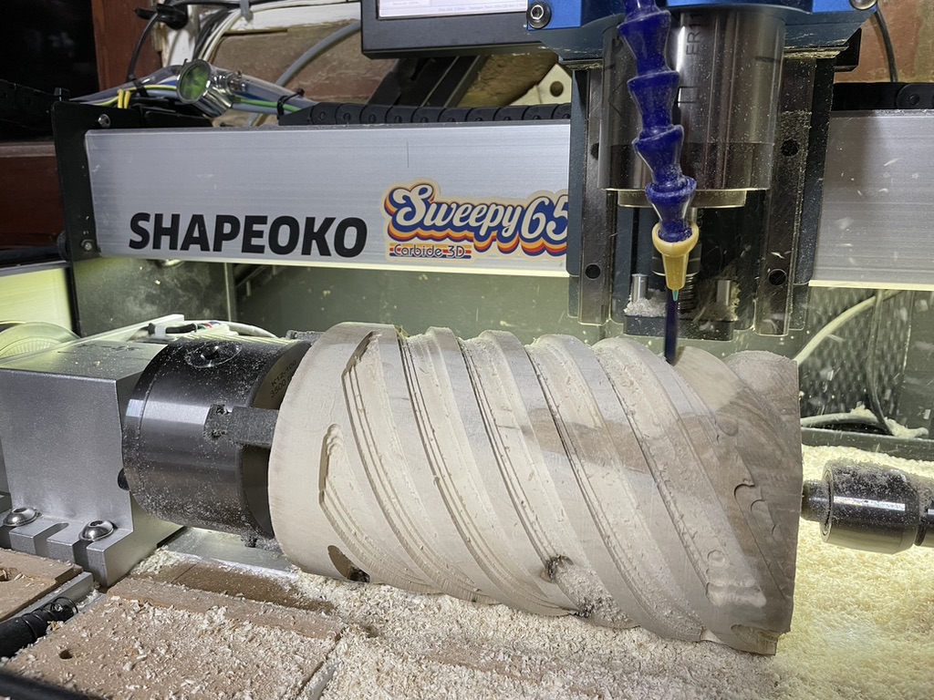
Referring to an earlier comment; I would like to try a 4th axis like this photo in the future
I got one of these, the exact same rotary mechanism from the picture. I mused over robbing the Y axis output to drive it, but realised that something has to hold the Y axis ‘solid’ to stop it moving in response to torque from cutting etc. So I replaced my (ShapeOKO) controller with a Teensy 4.1/GRBL HAL/External stepper H-Bridge drivers and now have XYYAZ (5 axis outputs in total).
I know it’s on a different machine, but the principles are very much the same. I use Vectric VCarve Pro, and like the simplicity of the Rotary design and output - and use Neil Ferri’s Post Processor in VCarve to get GRBL output that I can trust.
GSender passes through the Rotary GRBL without issue. The only hassle, which I have mentioned on this forum in the form of a feature request, is that there is no jog/position/read-out support for the A-Axis, even though the GRBL ‘stream’ is correctly and competently passed through to the controller by GSender.
Regarding costs and complexity: The most significant cost element was the rotary head itself - if I recall it was something around $200 US bought from AliExpress about 18m ago. The Teensy 4.1 module is $20, the break out board (Phil Barrett) around $40. Firmware in the form of GRBL HAL is open-source and, with the very useful documentation from the break-out board maker and the HAL project’s ‘spiritual lead’, was easy to configure and install.
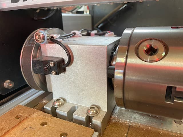
I cut a length of aluminium bar for the head and tail to index on, which neatly allows alignment to he held between head and tail once the tail is shifted towards any workpiece. This bar is fixed to my bed, the head stock is located on this and then fixed in place. The tail stock slides along and I have arranged threaded inserts at convenient intervals along the bed to hold it in place once positioned.
The rotary position sensor picks up on a steel cap-head screw tapped into the side of the large toothed pulley. The circular/blue device just above the sensor is unrelated.
@Hobbist I will try to get some more pictures. My workshop is being extended, so things are a bit moth-balled right now. The chuck head with pulleys and the tailstock came from AliExpress if I remember, although I think I have seen someone post a very similar product picture on Amazon a while back. The position/zero sensor is a spare one from my Carbide 3D ShapeOKO 3XL machine that I got in a maintenance kit - I like having it because otherwise setting zero needs thought every time (which position shall I call zero, do I zero before or after mounting the workpiece etc).
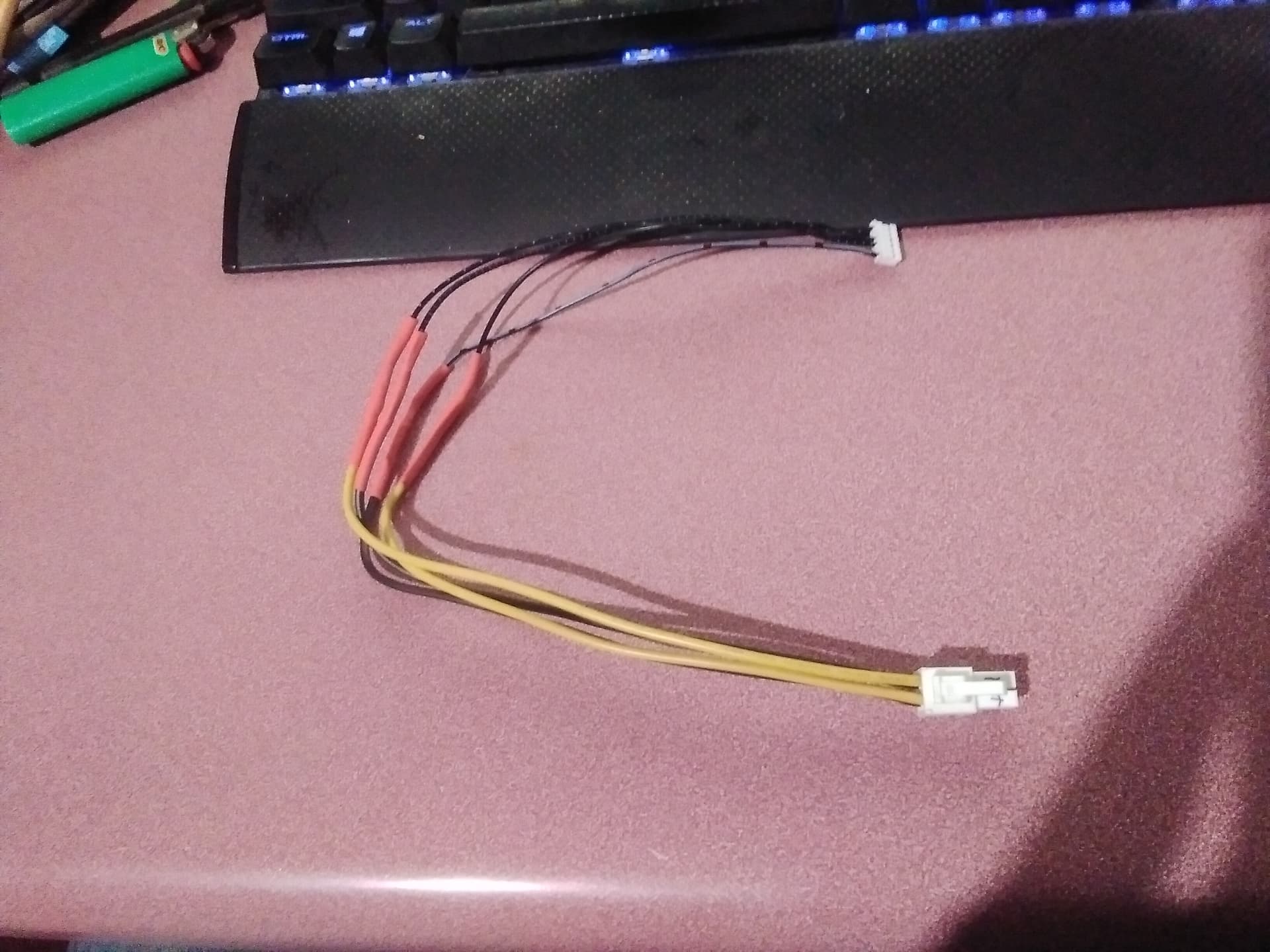
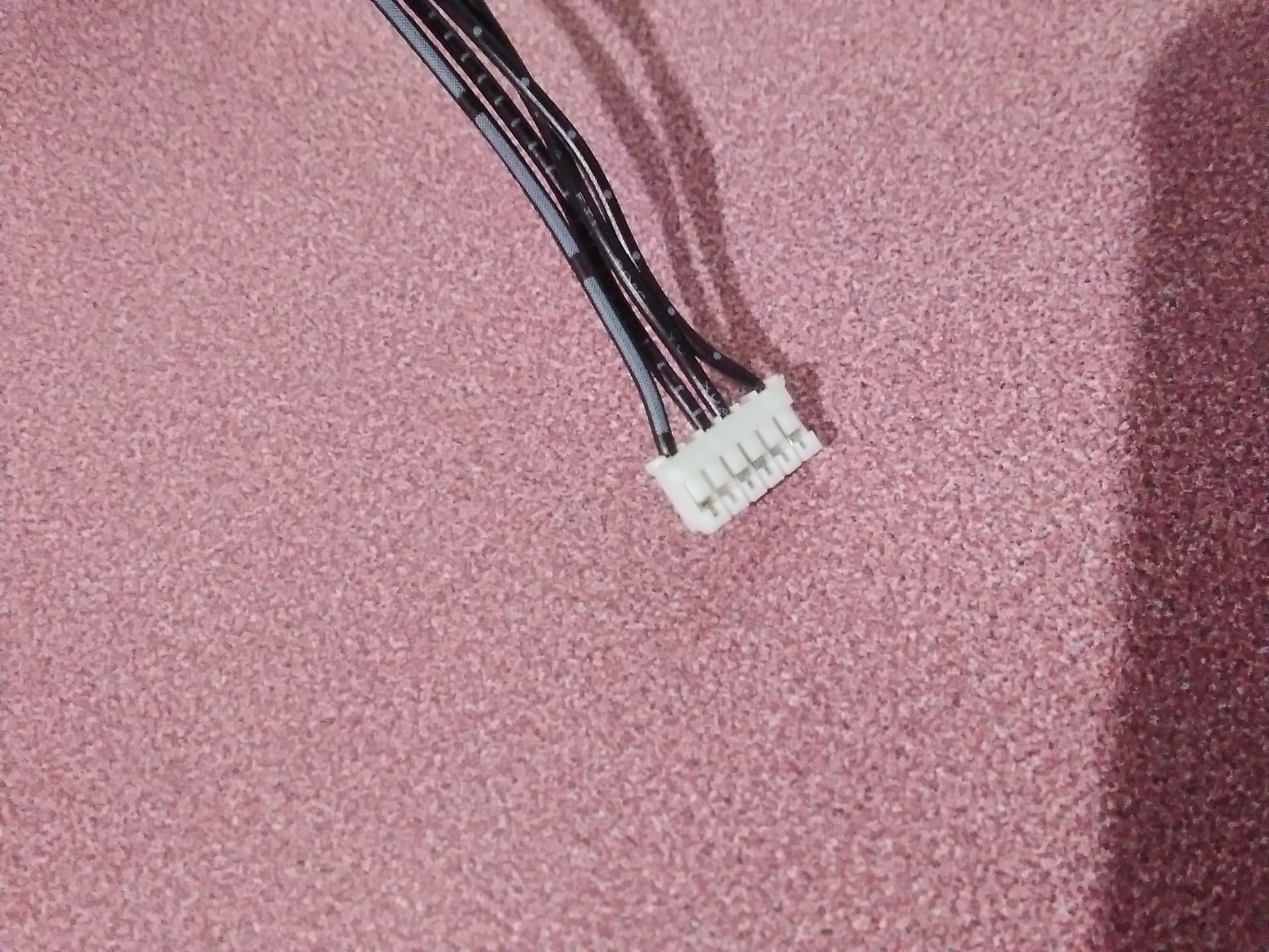
Here are some pictures of the cable I had to make. I misspoke when I said I attached it to the X axis. I attach it to the long Y axis cable and disconnect the other Y axis motor.
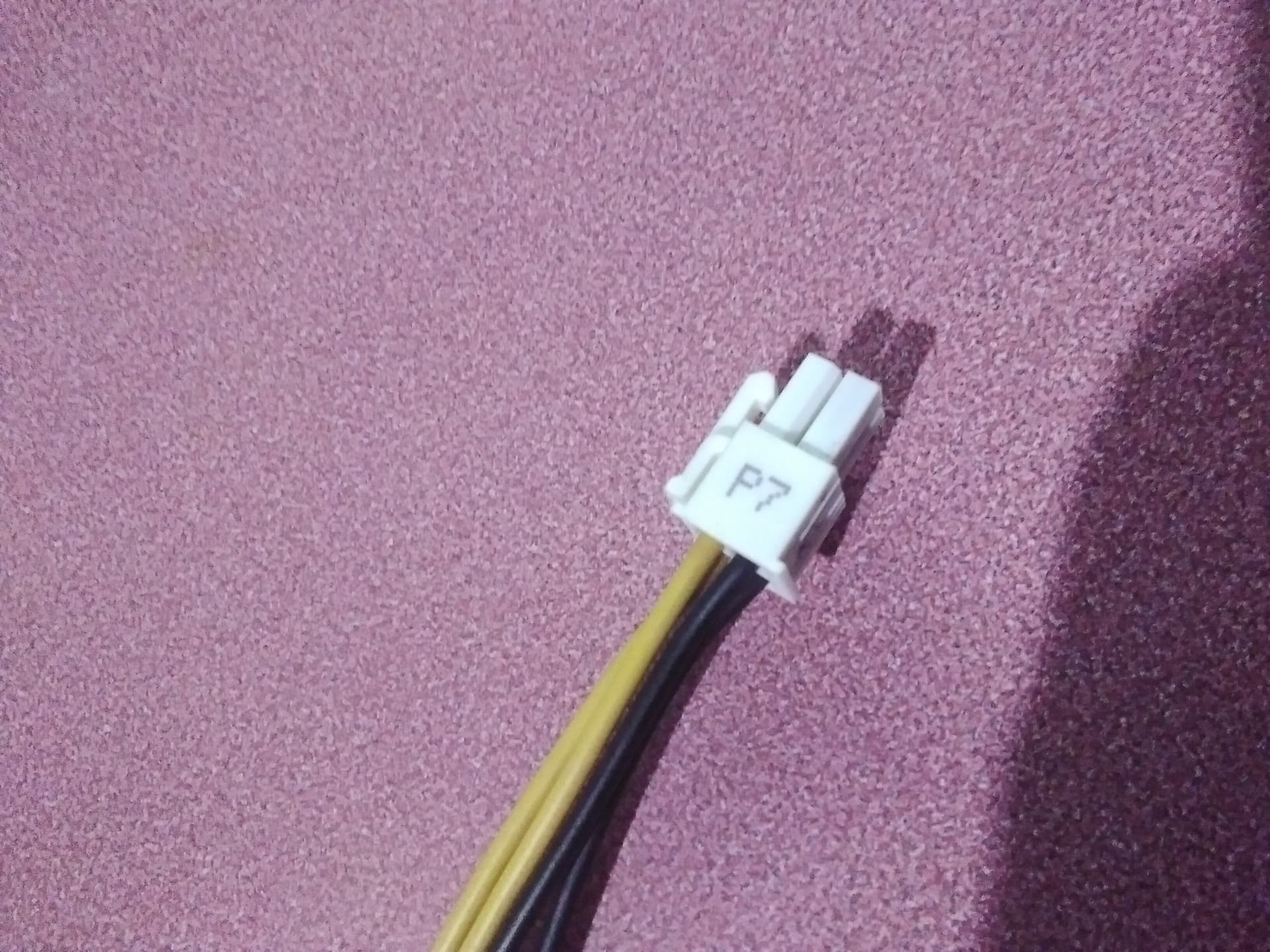
The other end I scavenged off from an old computer. I believe it is a 4-pin ATX connector if you have to buy one. You can recognize them because of the 2 square and 2 half round pins.
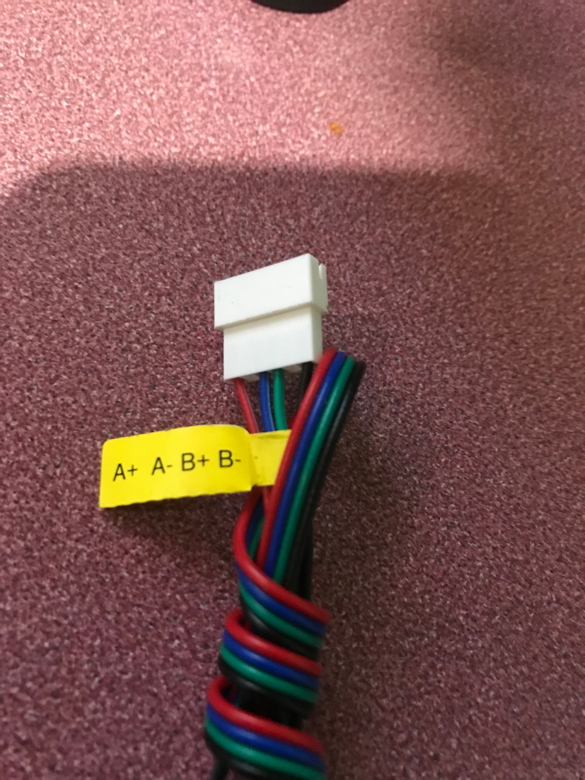
Do be sure to double check the pinouts so that everything is connected properly. I labeled all the wires with painters tape and a marker to make sure I connected them correctly.
The pins are labeled on the control box for the LongMill and the other end was labeled on the connector that came with the rotary. If your rotary is not labeled you might find it on the manufacturers website or the instruction manual.
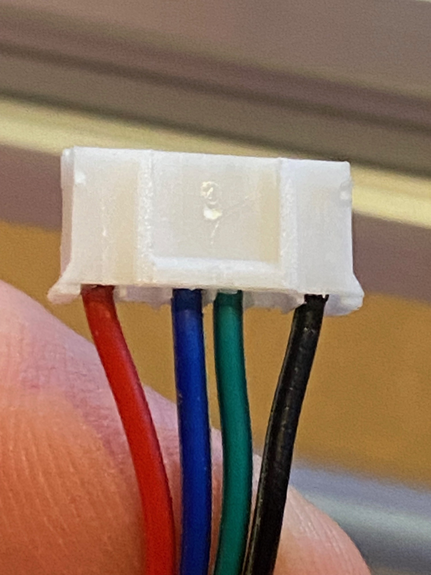
I’m doing the same thing and wondered if you could share the order for A+ A- B+ B-. The motor I have from Genmitsu is blank and the label on the wires doesn’t say which side it starts from. Looking at jfish’s picture, I’m assuming we have the same cable
Also, did either of you adjust the current setting on the longmill board to run the smaller motor? I think the Longmill is set to 2.2a and the book for the Genmitsu says 1.33.
Still have this plug in the box, it’s what I went by.
Didn’t do anything for the smaller motor, I thought/think that the smaller motor just won’t draw as much amperage but I am not an electronics expert by any means.
Thanks for the info. I was worried that label could be reversed, but mine is the same.
I’ll hook it up and try to lower the current also. Here is the page that shows how:
And this was an interesting page I found on the rotary install:
In the step 2 instructions it does talk about the NEMA 17 vs 23 motors and that lowering the current made it quieter and less heat. Probably more of a longevity thing than a work/not work thing is my guess.
June 22nd 2023: Longtime no see, people, many delays in my life.
…was Sep 2022 when I bulled in creating this Rotary Axis thread.
Now that I lucked up on this Vortex thing, though I am still not ready due to delays, I am going to rush my order and get the MK2 + Rotary Axis(Vortex) and all accessories right now.
I almost missed it, since the word VORTEX at the end of the menu did not trigger in my mind… should have printed (Rotary axis) below it in small letters.
…or the home page should have a flash space to show the Rotary Axis is now available! Lucky for me I was delayed… it saves me the 3rd party self made concoction… now it’s in the machine with support.
Thank you.