I’m attempting to retrofit a Shapeoko 5 Pro with the SLB, and am running into issues getting the C3D spindle (VFD) to work.
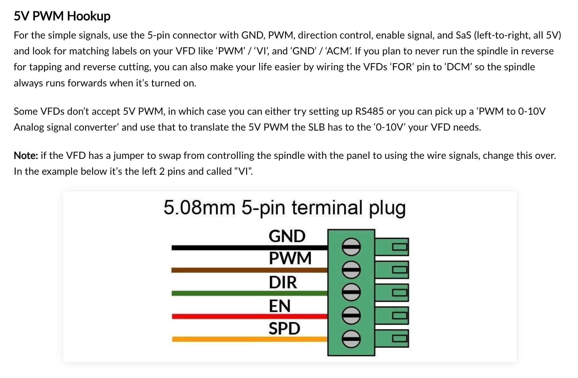
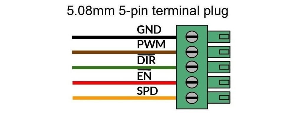
I have configured the SLB firmware per the Technical Manual 5V PWM Hookup instructions and I believe set up the firmware correctly. However, regardless of what I set the invert flags to, I can’t get the DIR or EN pins to do much of anything. I do see a signal on the PWM pin when I run an M3 command, so I believe I have the correct spindle selected.
Am I missing something here? Are the DIR and EN pins implemented or is this in the future work category similar to Y2 limit switches?
Also FWIW while looking for +5VDC to steal for debugging, the Technical Manual claims the TLS power pin is 5VDC, but when I measure it out here I see 24VDC. Not sure if the docs are wrong or my board is wrong, but the two don’t match in any case.
I have no SLB, so cannot be of much help being a reference to anything. I have looked into the schematics to find the Voltage thing you mentioned and found a selector section on the tls voltage.
I however am not able to locate R9/R10 in the board diagram for it is heavely labeled up and not the highest resolution. But, at least there is a why for the weird voltage swap. The question is, is this a fault on the board or a fault on the tech manual.
Anyhoo, here’s the link to the schematics on the SLB. You might be able to find another spot to steal your 5v (rs485?)
Oh interesting, thanks SE! I swapped R9 to R10 to change the output voltage for the limit switches, and I guess it changes the tool length sensor voltage as well, that makes sense.
Sienci devs, can you refer to this voltage in the docs as “accessory_Vcc” or something instead of magic numbering the text to “5V”? Clearly “limit_vcc” applies to more things than just limit switches.
Yeah fair enough on the labeling, it’s certainly changeable but it’s also something we know most of our users won’t change so 5V default tends to be a bit clearer. Thanks @Spamming_Eddie for chiming in to point to the schematic, it’s exactly what I’d point out too.
@drilling-vagueness has this fix remedied the issue you were having with your spindle communication?
I have been out all day so haven’t had a chance to look at the schematic. I still don’t see any activity on the enable and direction pins at either 5 or 24VDC, regardless of whether the firmware is set to invert the signal.
I assume that an M3 command should assert both EN and DIR, and M5 should clear them? Or is there more gcode involved that I’m not understanding?
For those pins in particular, you need to also make sure that the SLB_SPINDLE is selected as your current spindle. By default this should be the case, but it’d be good to double check. If you’re not sure, sending $i in the console should tell you what firmware version your board is running (5.0.5b is the latest for SLB, and 5.0.11 is latest for SLB EXT) so you can either update the firmware, or if it’s up-to-date then send the command “$rst=$” in the console and power cycle your board. This will revert the behaviour back to default and should give you the expected behaviour.
To be honest, if I were you, I’d contact our customer support to ask for a replacement board. No boards should be shipping out with 24V on the 5V line by default so it might be better to get a replacement now than to possibly find other issues in the future or spend needless time troubleshooting
Thanks @chrismakesstuff , I’ll give that a try today and make sure the correct spindle is selected.
Just to be clear, I followed the instructions in the Limit Switches section of the Technical Manual to convert from 5VDC to 24VDC out, as that is what the C3D system uses for their inductive limit switches. I’m not sure if it was necessary for the limit switches, but given that this change is possible on the SLB I thought I would make it to keep the electrical interfaces as similar as possible and per your point, try to avoid needless troubleshooting around limit switch functionality. They work great!
I only made the note above because the wording around the R9/R10 change is in the “limit switch” section of the manual, not also the TLS section, and hence my surprise when I subsequently measured TLS out and found it also at 24VDC. I believe everything is working as intended in this regard, the manual just needs clarification of all of the outputs that will change levels after the modification.
Apologies for mixing topics, I should have put this discussion of voltages in its own thread but it only just occurred to me now how these are all related. Maybe a way to clarify this would be to create a manual section called “Inputs/Switches”, and create sub-sections for Limit Switches, TLS, and Probe (and any others I’m not aware of) in there? That seems to be the common grouping/theme here. Then in the “Inputs/Switches” section, a sub-section that covers switch voltage, and expand in there why we might want to change from 5V to 24V, in addition to how to do it with the resistor swap.
After inspecting the board layout I do see that the limit switches are labeled VCC, while TLS is labeled with V+. Updating the silkscreen in a future rev to use SWITCH_VCC as the label on all of these would be great!
I updated the firmware to 5.0.5b, and reset the board with $rst=$.
I have the SLB mounted fairly low so I didn’t notice the PWM indicator previously. I now see it light up with an intensity proportional to S when I issue M3 commands, so that part seems good.
Indicators Switch 1 and 24V aux/pwr 1 also light up when I issue M3, and go out when I issue M5. That all seems normal.
If I throw the scope on the PWM pin, I see a signal that changes with S values but it’s down in the mV range and getting swamped by noise. Not sure what this is all about. Still not getting anything on spindle enable - the pin appears to float when the spindle is off (M5) and get pulled to 0VDC when the spindle is set to run (M3).
I’ve tried re-setting R10 back to R9 and see if that makes any difference, but no luck (aside from the switch ports correctly supplying 5VDC now.
I’m about at the end of my ability to diagnose what’s going on on this particular port. Everything else I’ve tried on the board seems to work fine so far (e-stop, motors, limit switches) so I guess it’s time to contact support. Thanks for the help here!
Eventually I’d like a spindle with modbus/RS-485 communications which I presume would work around all of this, but this is what I’ve got for now.
Again, I don’t have an SLB nor have a spindle, so I cannot be of much help. I do have somewhat 2 decades of experiance in electronics repair so can point towards a few points of interest and known problems of certain components. Other than that, diagnosing a board without having it on the workbench is.. meh..
So, I went back into the schematics, spindle ctrl. If I look at the enable line, it’s pretty much a opto coupler switching an open line towards ground. Just what your measurements show. Prolly the pulling up has to happen on the spindle side of things.
The pwm line is a bit less clear to me for it has a multitude of fail points but since you are measuring random static, while the indicator led seem to work you might want to concentrate on looking at loose pins on U4, U3, and the connectors.
Especialy these kind of opto couplers are known to not always solder as nice as they should due to bent or dirty pins, leaving them just hanging above the joint or embedded in flux residue. In either case you should be able to spot it fairly easy, but a small push on each pin of the component wont hurt.
Another point to look at are the gnd pins of the connectors. They are connected to a bit more copper inside the print and can have the tendency to not solder if the solder proces is a bit off (preflux or solder contamination etc)
When you are at it, check the pins of U3.
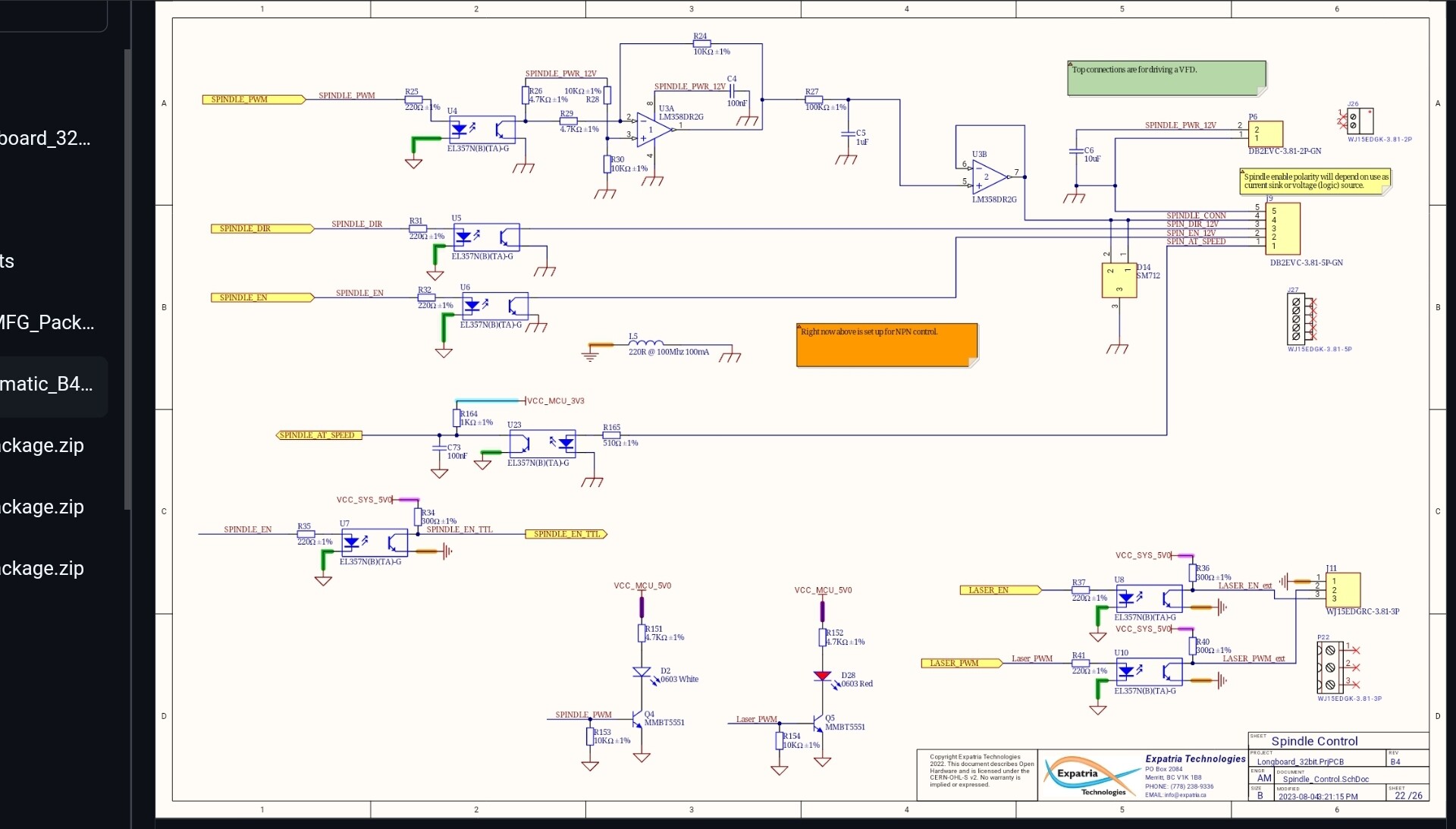
Here’s the schematic for the spindle section for some in depth trouble shooting.
Thanks so much @Spamming_Eddie! I appreciate all of the help even though you don’t have an SLB or spindle.
Issue 1- When I went to look at the schematic on github, I didn’t realize that github does it’s own pagination of PDFs and I was only seeing 3 of 26 pages. Now I realize there are a lot more
Issue 2- I did not specify that I’m working with the phoenix connector, as those seem to be the primary/preferred connectors on the SLB. From the schematic, I agree with you that it looks like SPIN_EN_12V is in fact a current sink. The SPINDLE_EN_TTL in the lower left of that page is a voltage source, but that’s only brought out on the AUX connector documented on p10 of the schematic.
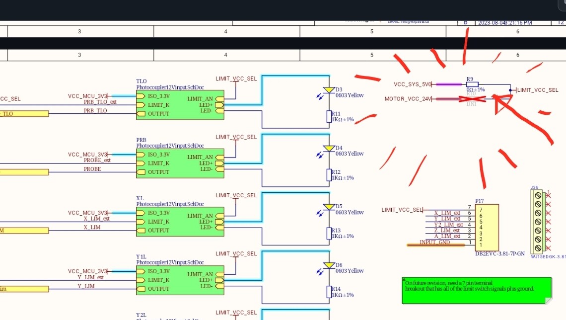
There’s are a few related notes in the schematic:
Top connections are for driving a VFD.
Spindle enable polarity will depend on use as current sink or voltage (logic) source.
Right now above is set up for NPN control.
I’ll have to do some digging on how this all works. I had assumed that the phoenix connector spindle enable signal was a logic level voltage, not a pulldown. I don’t know if that’s typically how controllers communicate to VFDs; it doesn’t appear as though this is how the VFD I’ve got communicates.
In any case … I would say this is tremendously under-documented in the Technical Manual section on 5V PWM Hookup? Or at least in my read of it.
The wording of this (“from left-to-right, all 5V”) makes me think that DIR and EN are also 5V logic level signals, not a pull-down. There’s no mention that the signal brought out on the AUX connector is not the same signal on a different physical form factor, but in fact a different logic format also.
@chrismakesstuff your commentary on the above documentation would be much appreciated. If the phoenix connector should be able to be configured as “all 5V”, can you please advise how to make such a configuration? From the schematic this doesn’t seem possible. If this is not possible, please update the documentation to match the as-built.
Well, if anything, you’re at least on track again. You seem more than capable to get going again. I too have been stuck on the github next page thing. Note that in the beginning you get next page but farther down the line that gets replaced by some kind of logo. It’s clickable for even more pages.
Hi @Spamming_Eddie, could use your analysis if you have a moment:
I dove into the board with a(n unfamiliar) scope, and after getting screwed up with the 1x/10x probe multiplier stuff finally managed to track down a PWM signal all the way to the buffer U3 (a TI SN74LVC2G17), where I see it on pin 3, but not pin 4. Ground and power looks ok on pins 2+5.
I assume this means I cooked the buffer somehow - it took me a while to realize that the spindle VFD wrapper/converter I’ve got expects a ground-switched / current-sinked source (not sure terminology, but more like the SPIN_EN_12V output of the SLB). I believe the signal converter is providing 5VDC on that line - would that be enough to kill the buffer output? Going forward I expect to have to bypass this board and just connect directly to the VFD.
It looks like the laser output on buffer pins 1+6 are still behaving ok. If it is possible to just re-program the spindle output to happen on the laser port that’d be fine for now, but this doesn’t seem straightforward in the firmware configuration.
In any case, I guess I need to get this buffer replaced. I don’t think this is a soldering job I’m able to do myself unfortunately, that package is tiny and I can barely do something with two leads let alone 6. Jeez, the SOT23 used here is the biggest package this device comes in
I do still wish all of this stuff was better documented outside of the schematic
I’m on my mob dev at the moment and it is a hassle to go back and forth between datasheets, schematics and posts so I cut right to it. Assuming you refering at U3, your datasheet does not match the schematic nor footprint of the package used on the board. It might be wise to look at this datasheet instead before concluding things based on measurements taken.
To be fair, the whole schematic part on the spindle has me holding back on stating with confident about the workings of that part of the board without the ability to comfirm suspicions into hard measurements. Things happen on the spindle side that are unknowns and with that, the knowns on the schematic side turn into black boxes aswell.
Looking at the datasheet for the lm358, I suspect it to be a sturdy fella, capable of handling a wee misvoltage at the ios (your 2G17 would likely not.) But then again, having a black box in those ios there is no telling.
Looking at the position of u3 on the board and assuming you have a station based solder iron capable of temp selection. (anything but a fixed temp iron) and a somewhat pointy tip. Replacing U3 should not be much more difficult that replacing a 402 or 603 resistor like R9/R10.
Removing U3: short the pins on both sides of U3 with solder. Use a tweezer to excert a !!small!! upwards pull on the IC. Melt the solder on the shorted pins untill the side pops up a bit. Remove the heat and wait for the solder to solidify. Move to the other side of the package and do the same handlings. Do this moving from one side to the other untill U3 is gone. Remove excess solder from the pads untill they are no longer shorted (doesnt have to be ultra clean.) Resolder the pins until nicely filled.
Replacing: Hold the new U3 on the pads and melt one pin on its pad. Push on U3 and visit the other pins with your iron. If needed apply a wee flux and revisit the now soldered pins one last time.
Seems like most of the misunderstanding is coming from what 5V signals are impacted with the jumper is changed to 24V? If that’s the case, maybe I could write up a new section in the docs to specify what happens if you change the jumper and the IO it impacts, is that along the lines of what you’re looking for @drilling-vagueness?
Sorry if you’re getting caught up on this stuff, I think you’re the first to use the 24V option on the SLB and I’d certainly agree the docs all lean more toward 5V since it’s the most commonly used - the jumper I put in as an option to hopefully provide more support across machines but up till now it didn’t seem like anyone was keen to take up that option
@Spamming_Eddie The lights were easy. The smoke machine burned out two IOT relays before I finally got it to work. The problem now is that the damn smoke makes it hard to see to change bits mid-job. I guess nothing’s perfect.
1- Not being clear from the technical manual which outputs are changed from 5V to 24V with the resistor R9/R10 change. I now understand this to be limited to switch I/O, and not affect other things. This isn’t really an issue; more of a red herring while I was trying to resolve spindle stuff and generate the correct signals for my spindle VFD. Specifically, it uses a 24V enable signal, so I was trying to generate/source that from somewhere on the SLB and the wording of the technical manual R9/10 swap made me think that it might also affect spindle enable. Note that I did in fact want/use the 24V outputs for the limit switches on my machine, so that part is all good.
2 - Not understanding which of the spindle signals are active high (PWM), and which are active low (enable & dir). I mistakenly thought that enable was also active high. I’m still not super clear when a design would choose one over the other, and I guess how to understand connecting multiple devices that don’t share both gnd and Vcc (the spindle port only has gnd on it). I guess normally active low signals are denoted with a bar or some other indication that they’re not active high:
This would have helped me understand that I shouldn’t have expected spindle enable to be +5V, and therefore wouldn’t also have been swapped to +24V per issue #1.
Again, none of this is really an issue with the board design itself, but more trying to follow the Technical Manual and finding it insufficient to help connect to devices that aren’t part of the Sienci family. The schematics and layout files have been tremendously more useful in this regard, but I don’t know that I’d expect most CNC router users to be able to read those, hence my interest in continuing to clarify and refine the Technical Manual. It also doesn’t help that my spindle control isn’t well documented, so I made assumptions I shouldn’t have about the universality of signaling between controllers and spindles. Specifically, I now believe the spindle PWM is active low and enable is active high at 24V which is exactly opposite of how the SLB is configured to work.
I’m happy to write up all of my findings once I get everything working (including gotchas) as I do think that the SLB is a significant upgrade from the stock controller that came with my machine, and I hope others will attempt the same upgrade.
And finally, many thanks to you and your support team helping me through all of this. At the end of the day, I just want to cut some parts