Is there any mechanical engineering reason you couldn’t design a router mount that has a slot cut in the rear bottom of the mount and fits over the vertical gantry plate and has threaded holes in the rear surface and through holes in the existing location?
So the idea is the bolts would go in through the front (presumably wings) of the mount with the bolt head facing out, pass through the vertical gantry plate and then lock down in to the threaded holes at the rear. This would be an uprgade from the current approach where the threaded holes are in the router mount itself and the bolts have to pass from the back to the front - with the bolt heads inaccessible due to the XZ gantry plate - making it very difficult to remove and lower the mount to the low position for carving or to switch mounts for a laser or other project.
I could be dead wrong on the engineering but I would think this would not only be easier to use but could improve the mechanical connection between the vertical plate for the Z axis and the perpindicular router mount?
For the lower location you would just need a second slot and holes. In fact, you could probably have more than two locations…
Z-HEIGHT UPGRADE?
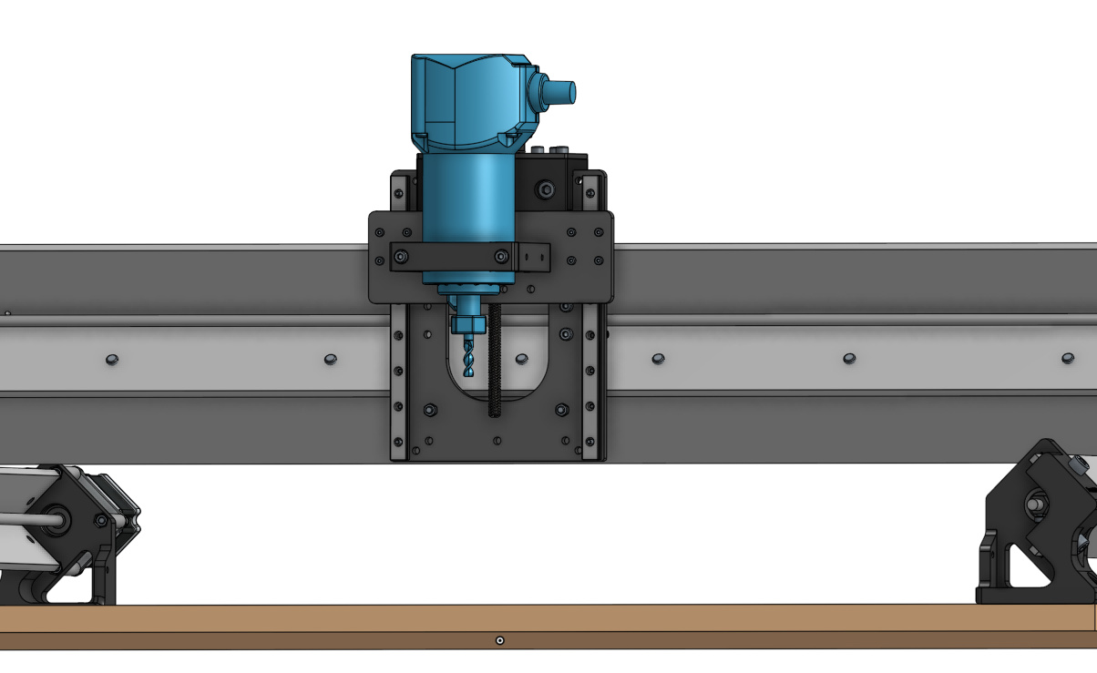
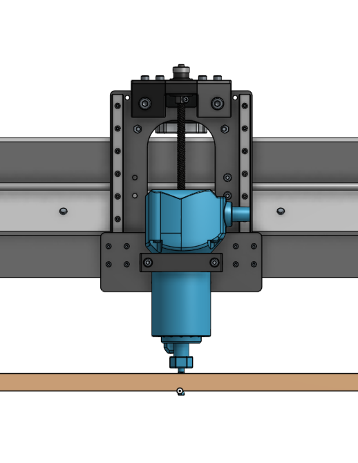
Which brings me to another question. Z-height. My over-active mind has been busy lately imagining different ways to use my Longmill but I am frequently running up against the Z-height restriction. Working with x4 lumber or even 1" baltic birch really limits the Z travel which can mean I can’t do things like chuck up a 3/8" drill bit due to it’s length.
I’ve also cut a slot in the front center of my wasteboard and have vertically mounted some x4 lumber and done some end grain joinery tests. However, the combination of bit depth (in my current selection of bits) and Z-travel limits things fairly quickly. Still, I did some basic tenon work fairly quickly…
I have seen some people put strips under their Y axis to gain Z-height but I am a bit concerned about reducing over rigidity doing that as the strips are no longer tied together.
Looking at the gantry plates, I was wondering if there is any reason Sienci couldn’t offer a taller version of the plates that fit on the existing design? That steel seems mighty beefy (love it). Could you go another 50mm or 100mm of travel and go to a longer lead screw? Or does the lever effect of having the router up higher relative to the rest of the machine start to become an issue at at that point?
If the mechanics work, offering a 1.5x or 2x Z-height option as a purchase or after sale upgrade could be a quick and easy way to further differentiate the machine. I think all the other parts except the gantry plates and lead screw could stay the same?
Hi Jeff would you be able to elaborate more on both your suggestions?
For the Z-height, at it’s highest there should be plenty of clearance for using even the largest of bits and at it’s lowest you shouldn’t have any issue using the smallest of bits.
Will do. I’ll fire up sketchup in a moment and whip something up quickly to show the concept and post a few screenshots.
On the Z-height, I’ll put together an example of what I was doing on the table and take a photo. Might be easier. But one example is using a 3/8" drill bit (which is quite long) to drill a grid of holes left me with 4-5mm of Z travel from the top of the workpiece (which was 19mm MDF). It took me a while to figure out what was going haywire when I first ran it, but of course the Z axis was crashing on retract. Adjusting at the heights down to equal <=4mm got it working, and I had to use a 1mm ruler as my Z zero strip.
Not knowing onshape, I whipped something up in SketchUp. Turned out to be a bigger job than I expected, probably should learn OnShape, but can only be angry at one CAD package at a time and right now that Fusion 360.
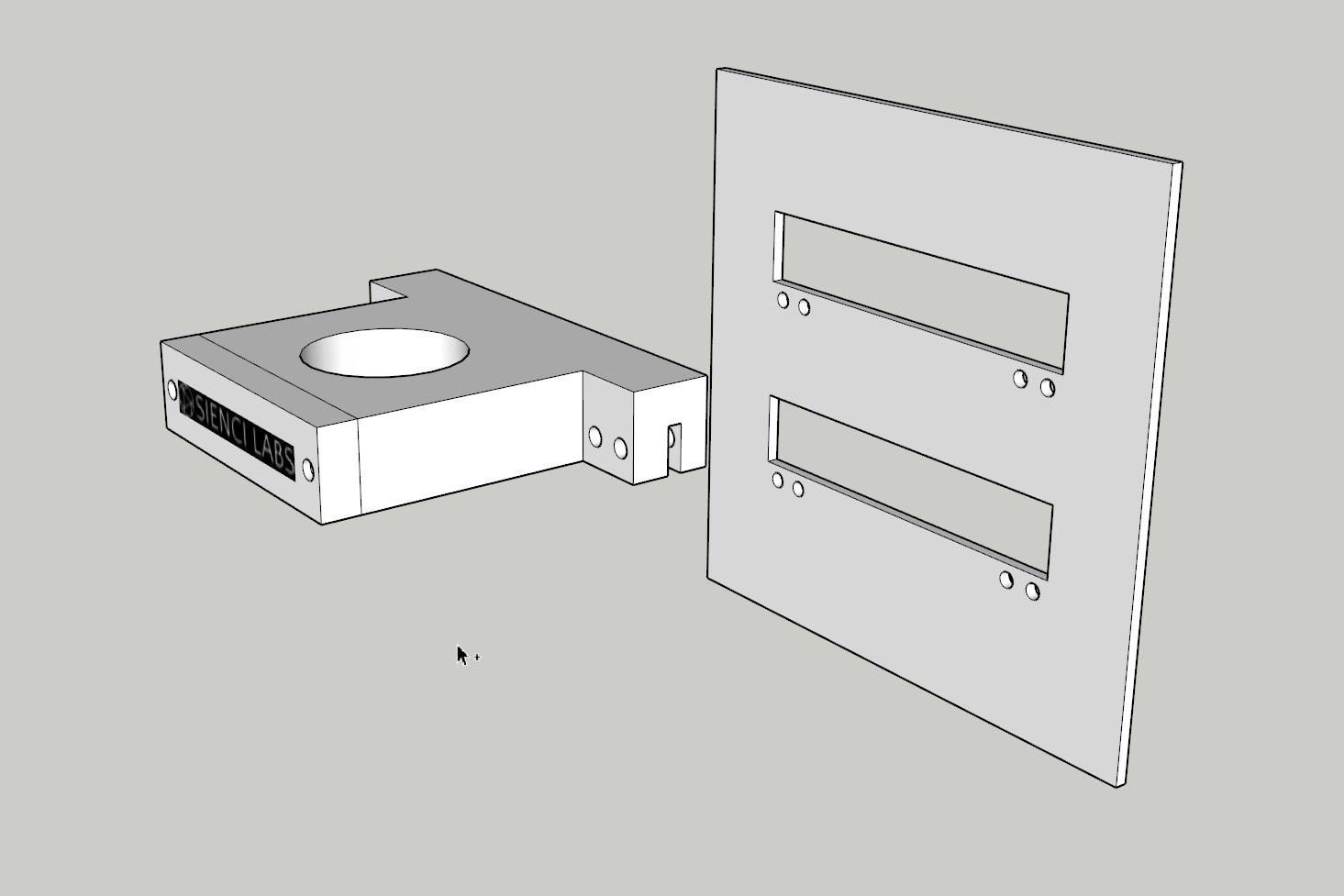
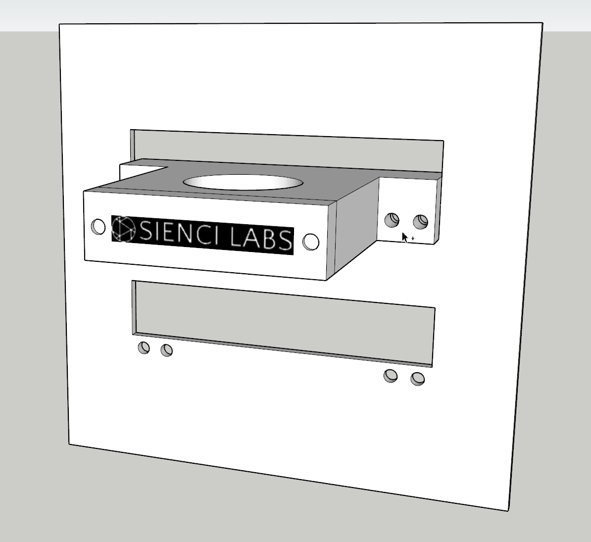
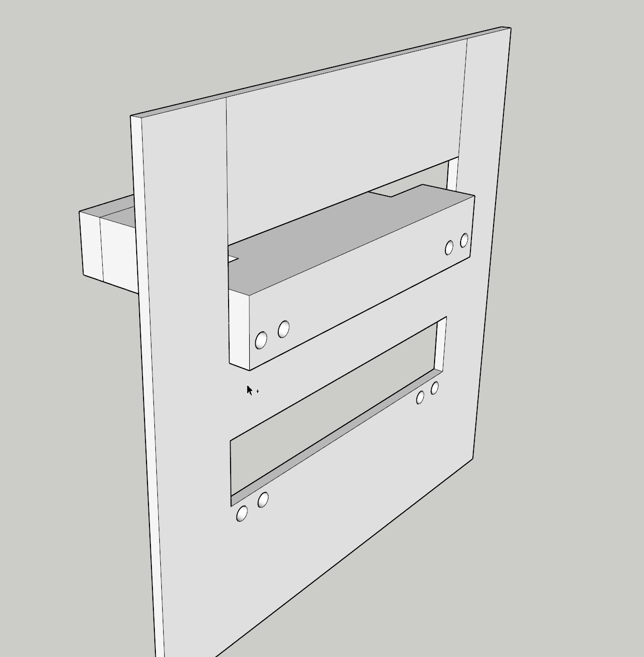
This is for concept and approximate positioning only, and for mechanical consideration so please be easy on me (dimensions, material thicknesses, hole positions). The goal was to be able to easy unbolt the router mount, from the front, raise it and slip it out and put it in the second position within seconds - while still maintaining lots of bearing surface with the vertical gantry plate. I’m sure there is a stronger and more elegant way to achieve it but again, concept…
Router mount and gantry plate separated, note inverted slot in read of router mount:
I can see this design being problematic. The gantry plate gets pinched in the router mount slot. This slot by necessity must be wider than the plate thickness. Torquing the mount screws down would distort the mount taking the router out of tram.
A better design might be a series of threaded holes in the gantry plate to locate the router mount at the desired height. This may require a thicker gantry plate to provide enough threads to prevent striping.
Another alternative would be a series of PEM studs in the gantry plate and holes on the tabs of the router mount. Attachment would be made with nuts.
A series of holes are an option but unfortunately that wouldn’t do anything to address in compelte inaccessability of the bolt heads once the XZ assembly is installed on the X rail. The number of positions is a second and useful discussion, but being able to move the position without requiring the removal of the wheels to make the change was more the thrust of where I was going.
I’m not sure I’m following you about taking the router out of tram when you torque it down. With four bolt holes through the same holes that are in the plate now, why would it be any more likely to be out of tram when you torque them down? [EDIT: I see what you’re saying. The slight gap required for fitment between the router plate grove and the gantry plate itself could lead to it being very slightly out of tram when torqued down. Would require some additional engineering to figure out a solution to that one. Good observation.]
The PEM studs are an interesting idea and would be convenient for sure. I suspect their breaking force is likely lower than through hole bolts though?
The series of holes would be threaded so the router mount could be attached with fasteners entering from the front.
PEM studs are every bit as strong as grade 5 fasteners. No problem there!
Your proposal would result in the gap closing up at the open end which would cause the router mount to tip down. the result is the bit would not be square to the table without some sort of adjustment.
Threaded holes or PEM nuts sounds like the way to go. But with threaded holes wouldn’t it still be prudent to have a nut on the back to ensure it doesn’t shake loose? In which case we’re back where we started?
You could use nuts on the back side of the gantry but as you pointed out it would make the entire exercise redundant. I would use flat and lock washers on the bolts.
Proper torquing of the bolts would go a long way to prevent them from coming loose. In many critical mechanical assemblies, the engineers specify fastener torque values that actually stretch the bolt or stud within it’s elastic limit. This provided substantial resistance to fasteners coming loose. The addition of a split lock washer provides even more resistance to the fastener backing off. Since the part being retained is aluminum, a flat washer between the lock washer and the router mount prevents the lock washer from damaging the mount.
It’s always a challenge for engineers, when designing a consumer grade product that requires assembly, to find the best compromises between best practices, costs and simplicity.
I would like to comment on the engineering and elastic limits are usually limited by friction of the threads and the contact points of the nut and bolt against the mating surfaces of the plate frame or washer. A very minor amount of Vaseline increases the holding force and reduces friction to the point that you can tighten a bolt down more while staying further away from the torque limits of the fastener. I went to college late in my life and the one thing I learned is that most engineers are the ones that will tell you 1001 ways that things can’t be done. Worthless. The 1 engineer you want is the guy that tells you how you can do something. Probably true of everything in life stick to the guys that help you figure out how to do something. I think there is some really good work on this thread.
So true. The challenge seems to be that most engineering schools teach not-invented-here, whether they realize it or not. Ideally the message is how you do it or where it is already available so you don’t need to do it again. The number of times I’ve watched otherwise excellent engineers dismiss a totally viable and existing solution, so they could re-invent the wheel (frequently without improving it), is substantial. And the cousin to that is explaining in detail why you can’t do something that is a viable option that someone else suggests, which is another by-product of NIH syndrome.
That being said, still learn a ton hanging out with engineers.
Jeff
@jwoody18 I was putting some thought into your recommendation here and I believe I’ve now solved the adjustability issue on the next version LongMill
Rather than trying out a variety of possible options - the fix that I saw was actually to just elongate the slotted profile on the X-gantry far enough that it should now be possible to access, adjust, and remove the router mount bolts from behind without having to remove the gantry assembly from the rail.
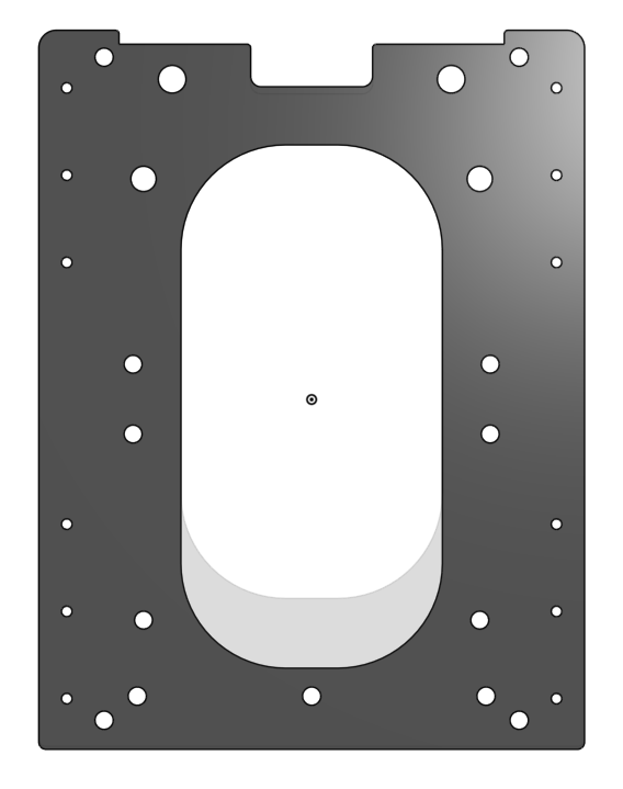
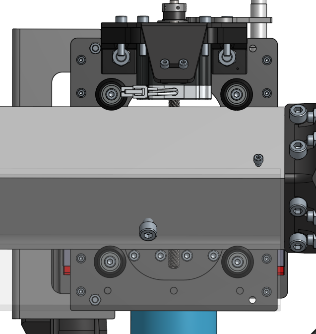
Here’s the comparison of the old gantry to the new one (the old one is mostly transparent):
You can only access one of the bolt levels at a time, but I think this is perfectly fine because you just set the gantry at the right height to remove all the bolts from the one height, then lower or raise the z-gantry to the other bolt line and reinstall them
@nuc_65 and @CRD, I’d be interested in hearing your feedback as well
Sorry for the delayed reply. I have been extremely busy and have not been on the forum much. As for your idea Chris, it seems rather elegant in it’s simplicity but it does reduce strength somewhat. That may be of little consequence but another option is a series of access holes rather than elongation of the slot.
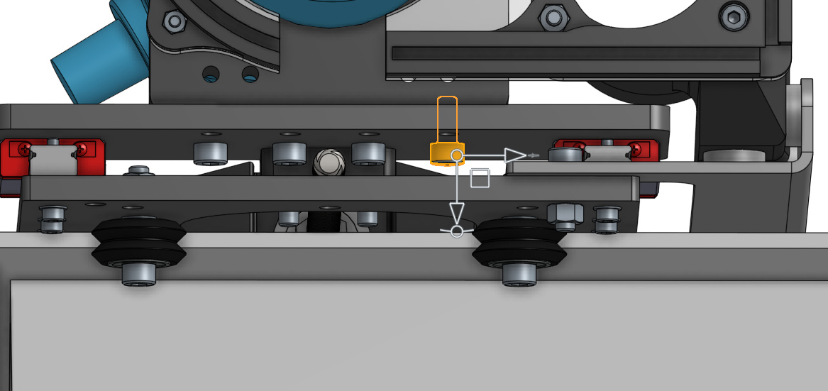
Luckily the stresses from the cutting tool to the router goes through the mount → z-gantry → linear guide blocks → linear rails → v-wheels so since the moment arm from the rails to the wheels is quite small I don’t believe the removal of material will result in a strength reduction due to lateral bending. The initial sizing of the plate was more overkill - the sizing of the slot was dictated by the extents of the movement of the anti-backlash nut. Though, something I did just in case was I added a bit more thickness at the top notch that you might be able to barely make out - just to ensure reasonable thickness top and bottom.
Access holes probably could’ve done the job just as well, but I think a more open area to access the bolts will probably make things less finicky.