If you don’t want to watch the video, the issue is that when I remove the probe and hit “Return to Zero,” the bit is level with the Z and Y axis, but overshoots the piece on the X axis by 10mm or so.
TnT, it sounds like you may have one of the offsets in the probe setup entered incorrectly. Check them against this chart Andy or Chris published. And make sure you have the Z probe distance/direction entered as negative.
I appreciate the quick response, but as I mentioned and shown in the video, I have all of the correct numbers. I’ll try it again today and see what happens
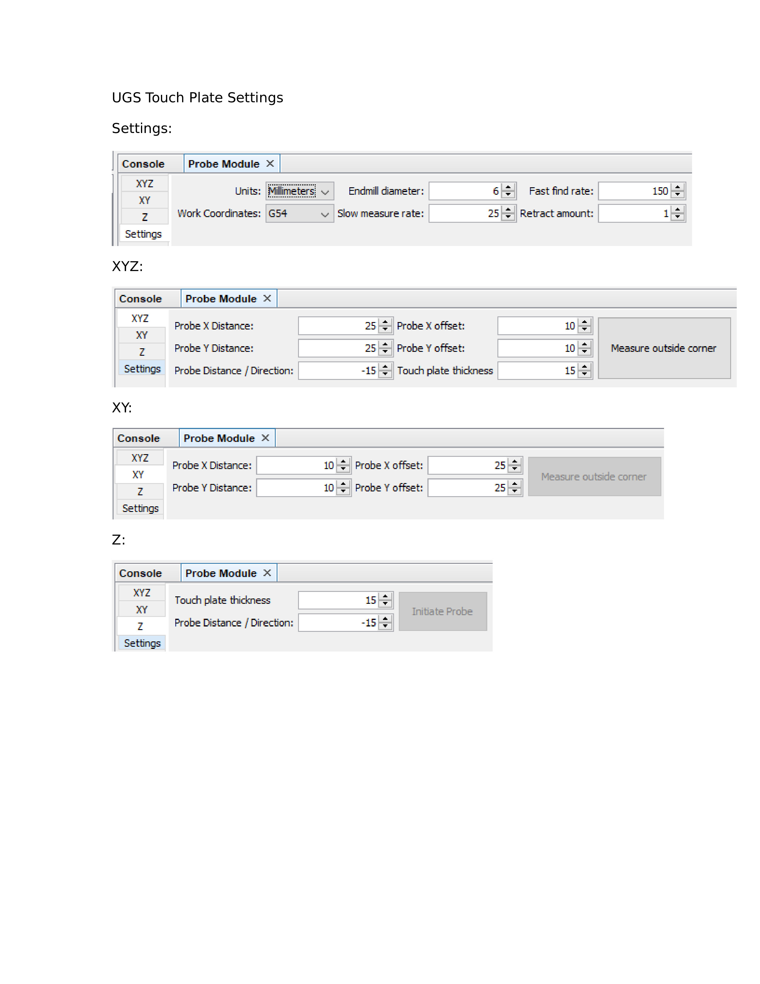
Bill: In the first chart, where you are highlighting the xyz settings, you show both the x and y “distance” as 25, which is correct. However, in your second chart, where you show only the x and y settings, the x and y “distance” are shown as 10.
This is the chart that either Andy or Chris published for setting up the touch probe. I went through each tab and set them up as the chart shows and they all work correctly, both for individual axes and combinations. I do find that sometimes the first time I use the probe after starting UGS the router moves to the wrong place, but after the first time it works correctly. I write this off as a UGS foible, not a settings issue.
In it, it clearly says that the probe x and probe y distance should be 25. I set them to that on the xy page of the module screen and on the xyz page of the module screen. It does not make sense to me, at least, that they would be different on the two pages.
Perhaps Andy or Chris could clarify this for all of us.
Grant and Bill, I think they are different because the starting point is different. XYZ starts over the circle on top. XY starts off to the side so doesn’t have to move as far. My view anyway.
I’ll will try adding on to this thread. I could not locate information for probe setting when using different sized endmills for a single job. I have a project that will use 1/4", 1/8", and 1/16" endmills to produce the detail in a carving. Do you reset the x-y position after each bit change or just re-zero the .z height after bit changes? This will be my first project where I am changing the endmill size and position will be critical to the success of the work. Also after using the probe macro, should it remember the zero point or do you have to click on set zero? I have had issues with the probe remembering where zero is. It might just be me new to using the LongMill. I am using UGS August 2019.
Chris - For the 1st toolpath bit set X, Y and Z of course. For the 2nd and 3rd toolpaths only reset the Z. But make sure the probe is on the same level as the 1st toolpath probe level. Remove the probe and then execute a “Return To Zero”. Do NOT do a “Reset Zero”. This works no matter what diameter bit you use on succeeding toolpaths. The “Return To Zero” will always move the center of the bit to the original XY zero position.
Thanks for the help. Wish me luck. I have produced a bunch of jigs and some simple signs so far. This project will be a large and complicated design for me.
I believe in your video you are using what looks like a 1/4" shank endmill, but it tapers down to a smaller cutting diameter. UGS is using the end mill cutting diameter to calculate your zero relative to the known dimensions of the touch plate.
So you’ll either have to enter the end mill cutting diameter or use a 1/4" endmill.
Also, you should be using 6.35mm instead of 6mm if you are using a 1/4" endmill for maximum accuracy.