I did a small file 1st rough cut followed by a finish cut of 1,661 KB.
UGS displayed that the file is too large (over 1 meg) and and error could occur, proceed, yes or no.
I did yes and it completed the job.
Is this normal and of concern?
Would CNCjs be better to use… I like UGS because of the Over ride tab so I can increase/decrease the feeds on the fly. I don’t see that in js.
But the main question is of the error msg I got for my 30x03 machine.
I could upload the files if wanted.
@astro4000 What version of UGS are you running? What program did you use for CAD/CAM. I’ve done lithophanes with gcode sizes of almost 4 meg and didn’t get that error.
Post your gcode if you like and I’ll see if I get the same message.
I’ve only played with CNCjs, but I’m pretty sure that the grbl widget allows for on the fly feed rate changes.
UGS Platform Ver 20190814 and it says it is up to date.
Note the large cut had a powerfail.. blew breaker because electric heater was on. But recovered the cut the best I could.
The file was a download, I did not create it.
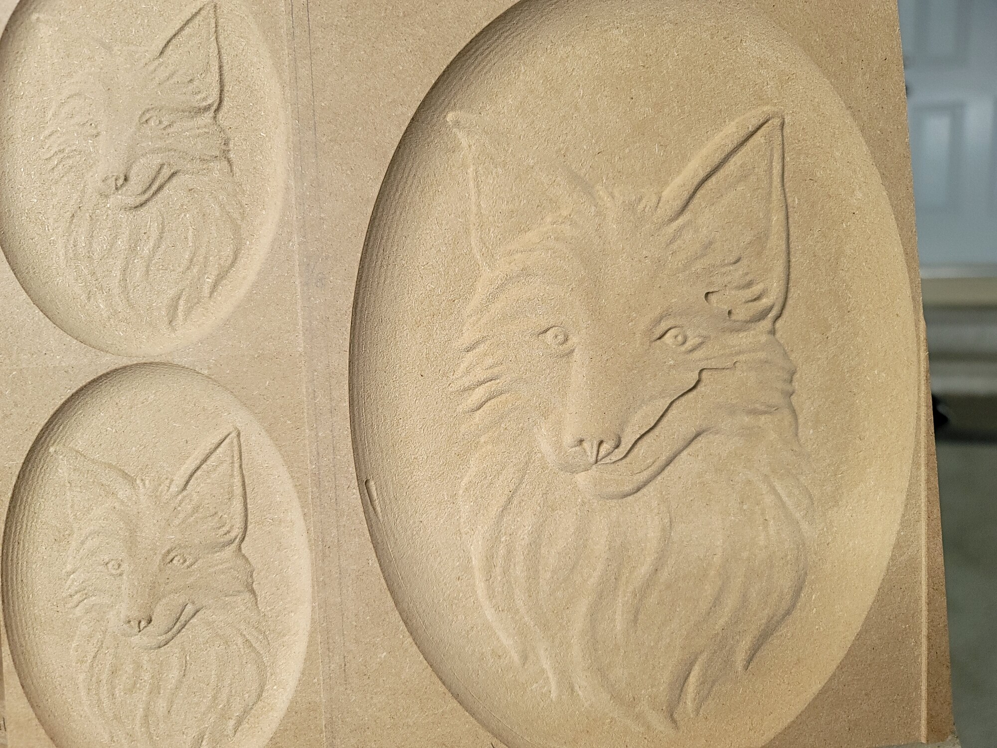
The original file is a fox head.RLF file 4,435 kb.
It is not allowed to upload here.
@Astro4000 - Alex, CNCjs does have speed adjustment controls as Grant mentioned. They are on the left panels below the connection and console windows. The large letter “F” is feed speed adjustment. Either up or down. Unfortunately power failures are hard to fix. Most of the time it won’t work. I’ve done some very large files in CNCjs with no problems or errors.
Also there is a later version of UGS that fixed some errors that were in the August 2019 release. I know there is at least 1 and maybe 2 releases for 2020.
@astro4000 A couple of things, Alex. As Heyward wrote, the version of UGS that you are running is about 5 versions out of date. If you want to update it, go here
In the leftmost column of the first chart of that page, under the bold heading " latest release (v.2.0.7), click on Windows and download that version. Before you do anything with it, uninstall the version of Java that you are running now. This download of UGS includes the best version of Java for UGS. As you know, UGS does not “install” as a normal windows program does. You just unzip it and run it.
All that said, I just tested your finishing file with a 2019 version of UGS and I did not get the size error message.
Are you using Artcam to generate the gcode? It should not matter; I’m just curious. ![]()
I got a copy of a macro to use in CNCjs for the XYZ probe utility. I ran in in js and it is way out of whack.
I like to use the probe block on the lower left part of the workpiece.
Attached is the copy of the macro. THe tool heads way over to the right instead of z down, well, anywhere but where I want to probe XYZ.
This is what I wrote as the macro in cncjs… I wish to use it once in a while just to have. I can do a stand alone z probe with included probe utility. OK No TXT files allowed so here it is below.
You can email me back alex@netpancom.com
;Set user-definded variables
%ENDMILL_DIAMETER = 6.35;in millimeters
%PROBE_BLOCK_Z = 15 ;Thickness of 3-axis probe on Z direction
%PROBE_BLOCK_Y = -40 ;Thickness of 3-axis probe in Y direction
%PROBE_BLOCK_X = -40 ;Thickness of 3-axis probe in X direction
G21 ;make sure we’re in mm
G91 ;Incremental mode
;======================================
; Set X Zero
;======================================
G0 Z3 ;lift Z 3mm
G0 X45 ;Move right 45mm
G0 Z-13 ;Move down 12mm
G38.2 X-25 F75 ;Probe X to the left 25mm
G0 X2
G38.2 X-25 F45 ;Probe X to the left 25mm
G4 P0.1
G10 L20 P1 X[ENDMILL_DIAMETER/2 -PROBE-BLOCK-X] ;Set current X location as negetive half the bit diameter
G4 P0.1
G0 X5 ;Move right 10mm
G0 Y50 ;Move back 50mm
G0 X-35 ;Move left 30mm
;=========================================
; Set Y Zero
;=========================================
G91 ;incremental
G38.2 Y-25 F75 ;Probe Y
G0 Y2
G38.2 Y-25 F45 ;Probe Y
G4 P0.1
G10 L20 P1 Y[ENDMILL_DIAMETER/2 - PROBE_BLOCK_Y] ;Set current Y location as negative half the bit diameter - 7mm thickness
G4 P0.1
G0 Y10 ;Move Y10
G0 Z15 ;Move Z up 15mm, should be 3mm above probe plate
G90
G0 X0Y0 ;Go to X0Y0
;=====================================
; Set Z Zero
;=====================================
G91 ;Incremental mode
G38.2 Z-25 F75 ;Probe Z
G0 Z2 ;lift 2mm
G38.2 Z-25 F45 ;Probe Z
G4 P0.1
G10 L20 P1 Z[PROBE_BLOCK_Z] ;Set Current Z as plate thickness
G4 P0.1
G0 Z5 ;lift Z 3mm
Alex
@astro4000 - Alex, no need to email. You have set bit diameter to 1/4 inch which is ok. But your probe block sizes are incorrect if you are using the Sienci probe. The Z probe block is ok at 15 but the X and Y are incorrect. Both should be set to 10 (not negative). The negative numbers are throwing you in the wrong direction and are way too large. Give the 15 10 10 a try and see how it goes. PS - don’t change anything else in the macro.
@astro4000 (@gwilki) - Alex, I just looked over the macro you posted. That is not the right macro for the 3 axis prob from Sienci. Here is the correct one below (and I already set the parameters). So just copy it and put it in CNCjs. Looks like you copied the 3 single axis macros and combined them. That won’t work as you have experienced. My apologies as I should have looked at it closer.
copy from next line to the bottom
(start with the end mill 15mm ABOVE the plate, about 15mm or less from bottom left corner.)
; Set user-defined variables
%ENDMILL_DIAMETER = 6.35 ;in millimeters
%PROBE_BLOCK_Z = 15;Thickness of 3-axis probe in Z direction
%PROBE_BLOCK_Y = 10 ;Thickness of 3-axis probe in Y direction
%PROBE_BLOCK_X = 10 ;Thickness of 3-axis probe in X direction
G21 ;make sure we’re in mm
G91 ;Incremental mode
G38.2 Z-25 F75 ;Probe Z
G0 Z2 ;lift 2mm
G38.2 Z-25 F45 ;Probe Z
G4 P0.1
G10 L20 P1 Z[PROBE_BLOCK_Z] ;Set Current Z as plate thickness
G4 P0.1
G0 Z3 ;lift Z 3mm
G0 X-25 ;Move left 25mm
G0 Z-10 ;Move down 10mm, should be 7mm below probe surface
G38.2 X25 F75 ;Probe X to the right 25mm
G0 X-2
G38.2 X25 F45 ;Probe X to the right 25mm
G4 P0.1
G10 L20 P1 X[-ENDMILL_DIAMETER/2 -PROBE_BLOCK_X] ;Set current X location as negative half the bit diameter
G4 P0.1
G0 X-10 ;Move left 10mm
G0 Y-25 ;Move forward 25mm
G90 G0 X5 ;Move to X5 (absolute) - will put you 5mm to the right of left edge of stock
G91 ;incremental
G38.2 Y25 F75 ;Probe Y
G0 Y-2
G38.2 Y25 F45 ;Probe Y
G4 P0.1
G10 L20 P1 Y[-ENDMILL_DIAMETER/2 -PROBE_BLOCK_Y] ;Set current Y location as negative half the bit diameter - 7mm thickness
G4 P0.1
G0 Y-10 ;Move Y-10
G0 Z10 ;Move Z up 10mm, should be 3mm above probe plate
G90
G0 X0Y0 ;Go to X0Y0
Thank you ! That worked great!
Just a question as I get more familiar with raw gcode.
What do I change for a 1/8" bit (3.175mm)
THen a 90 or a 60 degree vee bit… thats a different story. I think I would do a 1/8 probe then change to vee bit and do a Z probe only as X & Y already set. Am I on the right track for the vee bit?
@astro4000 You would change this line
%ENDMILL_DIAMETER = 6.35 ;in millimeters
You are right. Don’t use a v bit to set x and y. You want to use a straight bit.
Thank you
I kind of thought that was it.
(looking for difficult changes in SIMPLE solutions) Make sense.
I was using a 1/8" Aluminum soft wire/rod for test bit. It bends, bits break! $$ lol
Alex