Ultimate Altmill Drawer Cabinet

Here is my application of my “Ultimate Alt-imate” Altmill. Since I started using my Altmill in March of 2025, I was thinking how I could install a drawer underneath the table. Drilling and tapping into the aluminum supports sounded good for a while, but the holes might waller out and drop the drawer at the most inopportune time. So I did nothing. When I saw the You-Tube video of Scott building his drawer unit, I was immediately on board with this. His work then became my inspiration to make my Altmill more usable.

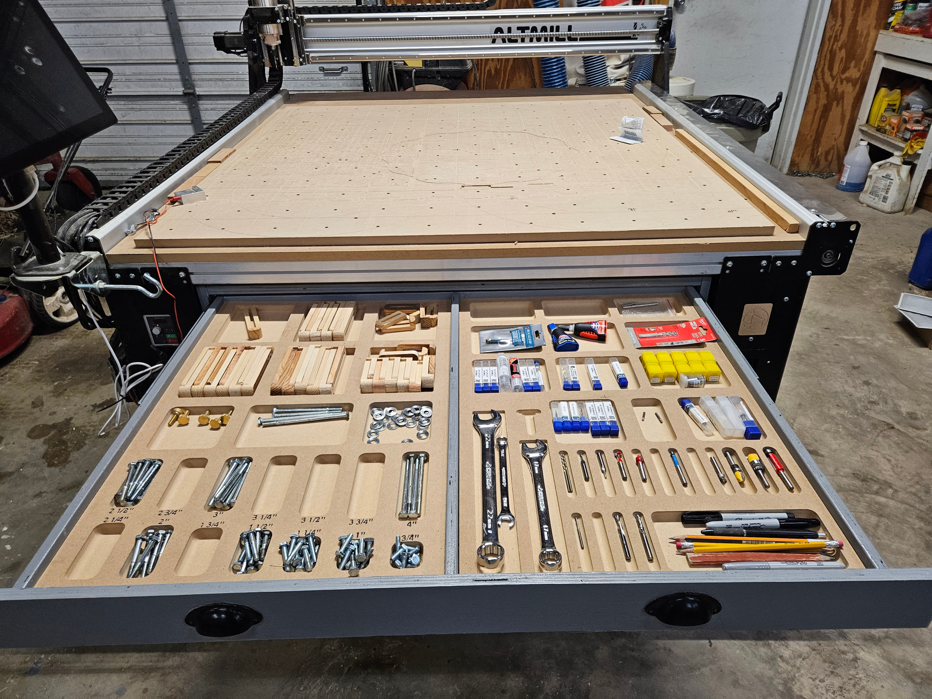
I don’t care for bit holders that hold bits vertically, so I didn’t care for a deep top drawer. I chose to make 4 drawers, 2”, 3”, 4”, and 5”. I used the box gadget in Vectric Pro and modeled a drawer 28” by the width (~38”) and 8” deep. I used a joint width of 3”, then copied it to a layer for each height of drawer. The geometry had to be massaged a bit, but once I did one it carried along for all the others. I added rectangle cutouts down the center of the bottom to catch the center stiffener. I also added several .30 diameter circles that I cut with a V bit. At each of these countersinks I added an 1.25” screw. I made the drawers out of 5/8” plywood.

I modeled the drawers and the box in Vectric. I attached the drawer slides in the center of each drawer. Analyzing the model gave me the dimensions for where to attach the drawer slides to the side of the box. I had the drawer slides installed before I built the box.

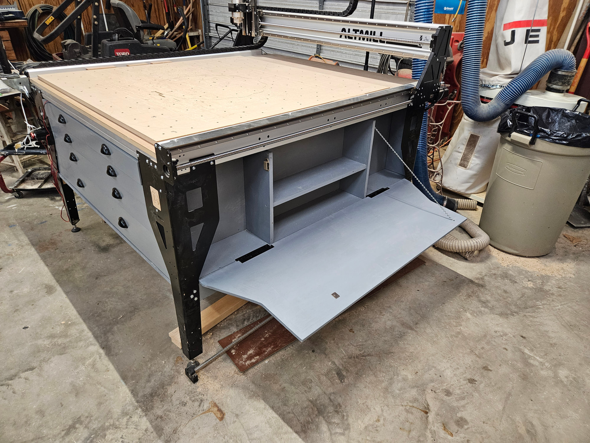
I did not use the mill to cut the drawer fronts. I removed the box, cut the board to fit in inside the legs, then marked it with a pencil and cut it using a jig saw. I did the same with the side tip out panels.

The side tip out panels have a special hinge. I did not want a hinge that would attach into the edge of the plywood. These hinges have the attach points on the inside back face of the tip out panel. These hinges are called a Marine Boat Offset Hinge. I got a size that offsets for a 1/2” thick ply.

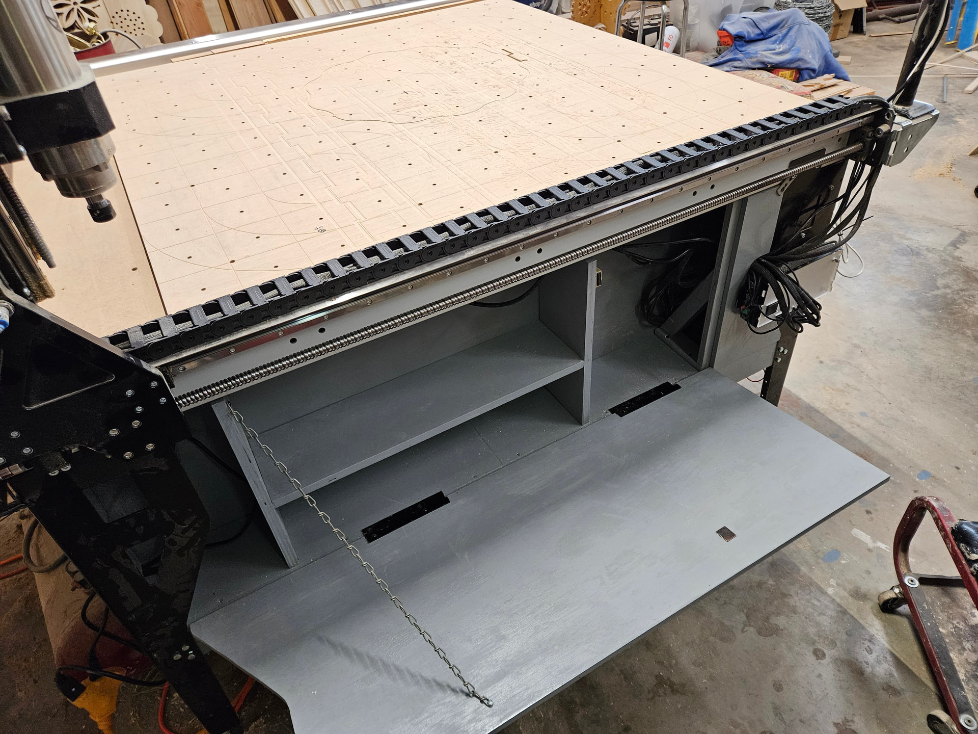
The left side tip out panel I cut about 6” from the front leg. I did not move the control box, but left it as was. I did relocate the E stop button to the front side, using a board behind the triangular hole to attach it. I gives me a little comfort if I need to use it I will be able to hit the button sooner after the crash than if it was around the corner. I made a simple wooden corner angle to fasten the little piece and be a stop for the tip out portion. All of the wiring is stored behind the small piece, kept in place by this angle.

I live in Texas, the county south of Dallas. The plywood I used was purchased at The Plywood Company of Ft. Worth. I bought Baltic Birch plywood, 2 sheets of ¾, and 4 sheets of 5/8. I needed one more sheet of 5/8”, but didn’t want to drive almost an hour for one sheet. The side tip out panels were made from 1/2” sanded ply from Home Depot. Made in Ecuador, what I call mystery wood, but it worked well.

I did not build the clamp storage feature. I did not build the gControl Computer pieces. I have not yet made the under machine sled – not yet.

The plywood had me learn a new math – I call it Plywood Math. Here is how it works,

3/4” plywood is .700 thick

5/8” plywood is .600 thick

1/2” plywood is .470 thick

One suggestion for someone starting this project is to check each edge of the legs for plumb. I had a couple of legs a half bubble off. It wasn’t much, but I fought this the rest of the way through. It is not noticeable now, and I’m not going to tell anybody about it. I mention this for a friend, okay?

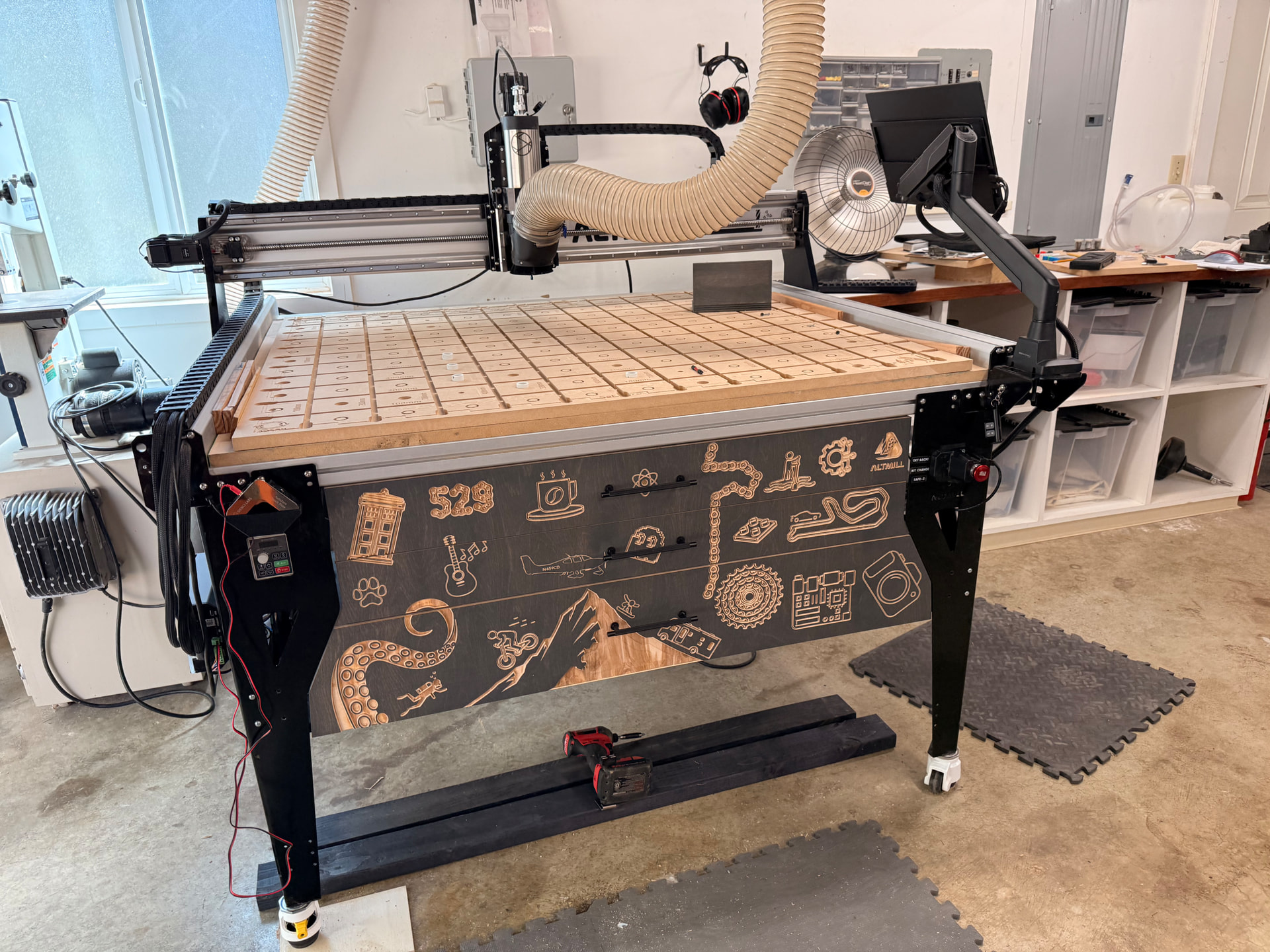
I am now choosing what is worthy of top drawer status, and so forth. The top drawer has MDF bottoms pocketed for worthy items.

Like most tasks, the hardest part was starting the project.

One more thing I am pondering involves the touch plate. I use the touch plate to set each cutter only for Z. It used to sit on a shelf near my left knee. Now it sits on the corner of the table. I’d like a little cup like a pocket watch holder that will attach using one of the table attach screws. Has anyone made a holder that keeps the touch plate out of the way but easily ready for use?
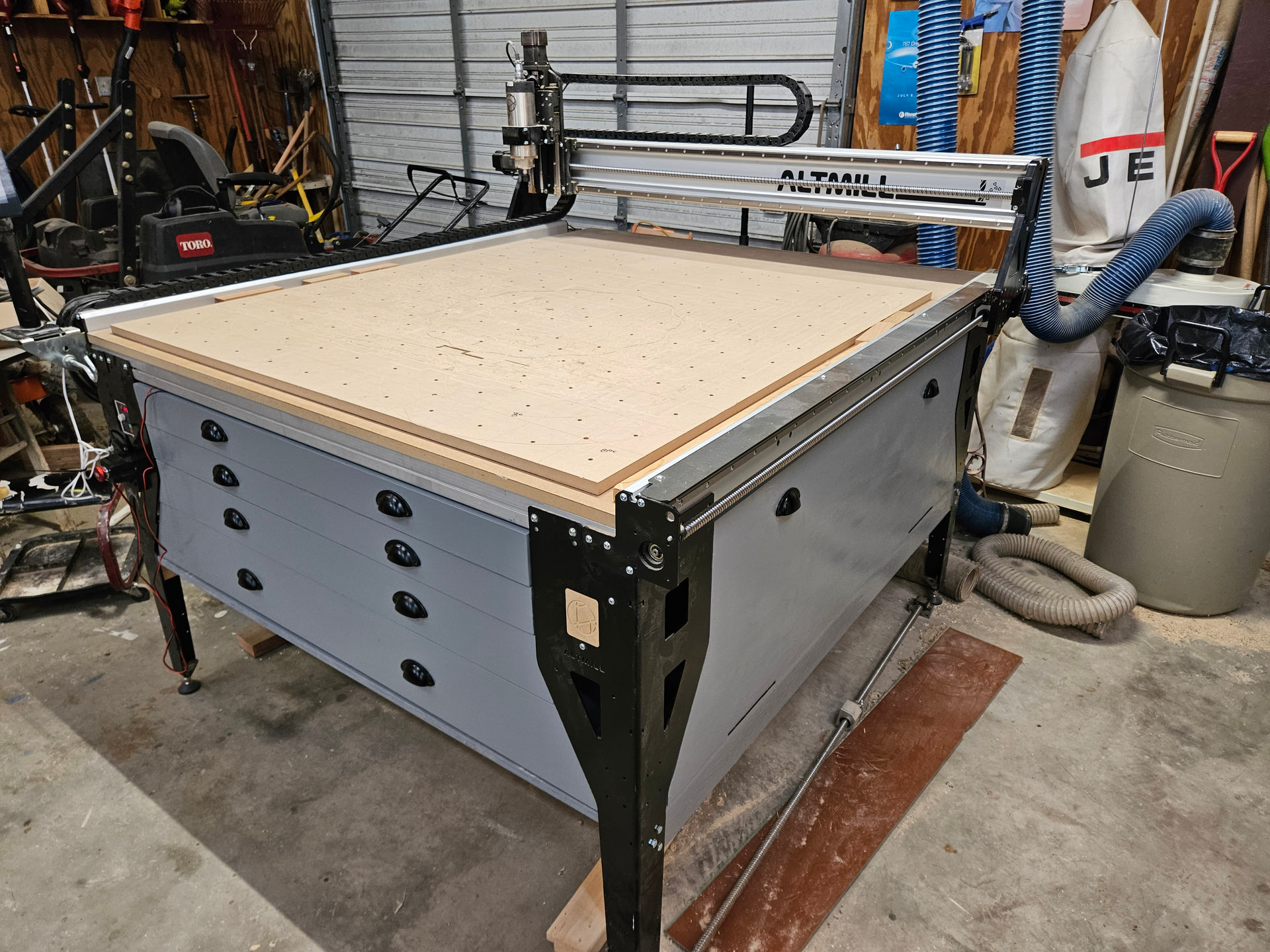
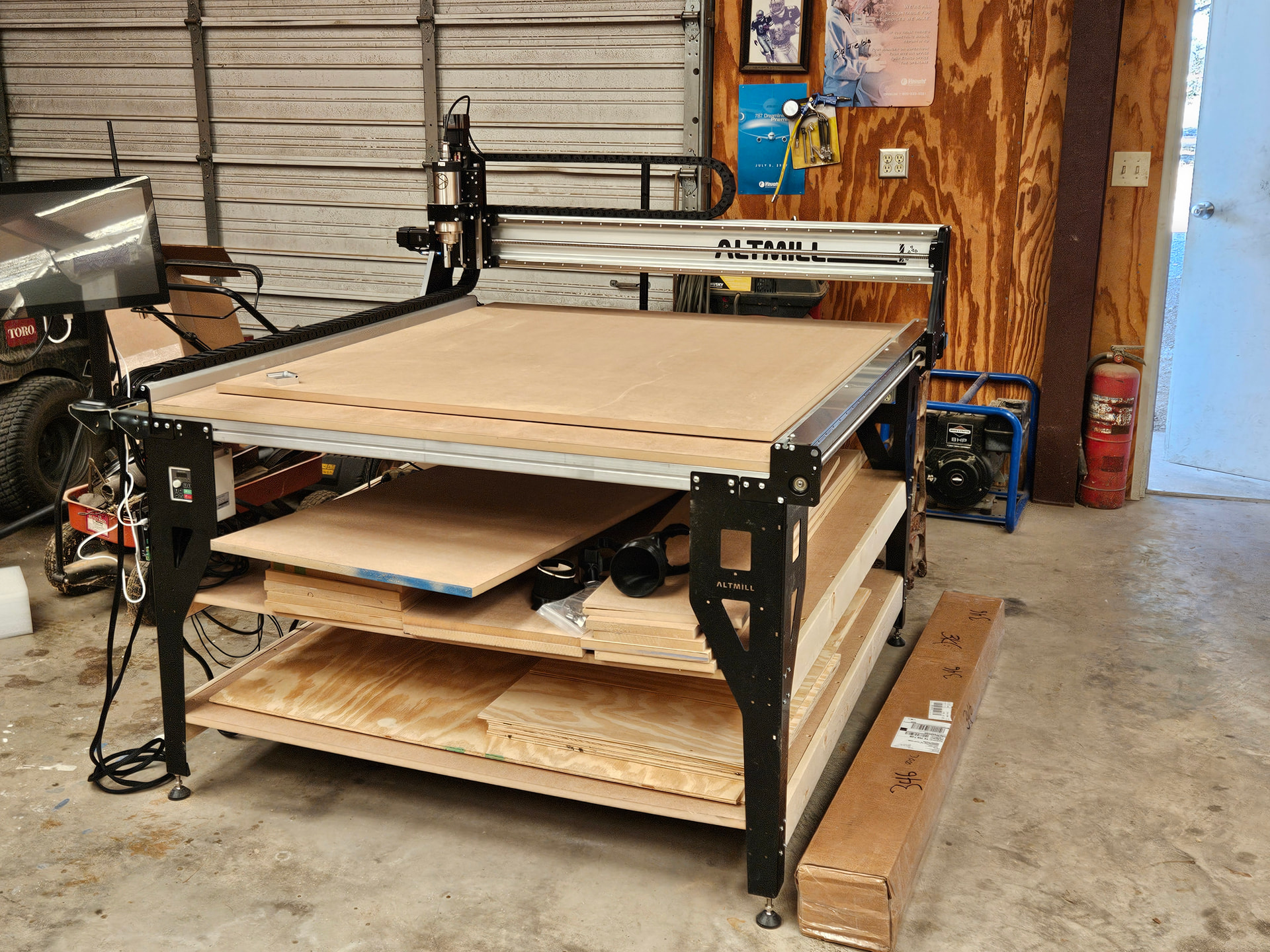
A before photo.

All after pictures.

11 Likes

This is looking mighty fine. Great Job! In regards to the touch plate holder, I hope one day they do something about that. Even if they sold it separately I would buy one. Although the black and red probe leads need some real work. The black lead’s magnet falls out very easily it seems. You can super glue it back in but it is sketchy since the glue can insulate the lead and disconnect. Hopefully they will redesign it to be screwed in instead of being hobby glued in at the manufacture. Like I said, this cabinet looks mighty fine!

I designed this: https://www.etsy.com/listing/1811580246/keep-your-workspace-tidy-with-the-custom

Happy to work with you if this design does not meet your needs. I’m in Tarrant County btw so just a little North of you!

2 Likes

@Eddie.Arnold @Karver_One I cut the my first touchplate holder out of MDF on my Long mill. It was good design practice. Now, I have a small 3D printer and I’ve printed a fancier one with a built in steel washer that the probe magnet can shtick to. That one, too, was good design practice.
I don’t know what CAD/CAM application you have. But, in any of the more popular ones, you can design a holder specifically tailored to your needs.

@Karver_One On the Facebook page, a user recently posted his 3D printer model for the auto touch plate. It mounts to the front of the cross rail, in one of the t-slots.

Look under the Files section in FB.

It’s better than my holder, which is currently the floor.

2 Likes

Sorry, I’m lost… Please post the URL for the FB auto touch plate.

Here are a few printable plan for the AutoZero touch plate including one that uses magnets to put it on the legs

2 Likes

@Jgt1942 https://www.facebook.com/groups/mill.one/permalink/2376343026170348/

Thank you! These are great.

Nice Job….but I gotta ask….are you still singing?

Very nice job! Inspirational! Thanks for sharing.

Has anyone managed to extract a DXF of the front of the Altmill Mk2? (The VCarve files of the Ultimate AltMill are for the Mk1) I tried to do it from Onshape but something didn’t work it’s the correct width at the top, but down further it’s off by almost 2" in the width I’m trying to use, so I’m pretty sure if I use to carve out my drawer fronts it won’t work ata ll.

@gremlin Yes. I posted them somewhere on this forum.

@gremlin nvm. I thought you meant the logo. The outside of legs should be perpendicular so I’m surprised the mk2 and mk 1 files would differ. The inside of the leg is different though.

@gremlin Pretty sure this is correct for the front and back. The spacing at the side is different.

When I did my plywood stiffeners, I used the drawings. When I went to install them, I noticed a gap between the leg and the plywood at the bottom. Tthis meant the drawings were wrong or the legs weren’t perfectly perpendicular to the table. It turns out it was the legs that were not perpendicular. There’s a lot of racking force at the connectors so it doesn’t take much movement for the legs to go out of square.

Table Legs - Table Leg.dxf (197.3 KB)

Thanks I was talking about the inside as I’m looking to make the drawer fronts.. I checked and my legs are plumb to the floor, so I think I’ve got them straight.

I just checked your drawing, and it’s the same as what I got out of the model, and not correct with my altmill, I’l have to go check all the legs again, as mine measures slightly less distances across than what I get here, I think it’s more like 46.5" instead of 48" on the inside.

So I went and checked, one leg is totally plumb the other is just sligthly off, but not that much, if I move the level out from the leg until it’s level it’s like 1/8" from plumb 20" down the leg. I measured in VCarve the inside set of bolts holes where the lower cross beam would be placed and this diagram shows that to be 50.25" I measure 49.25" on mine, so it’s an 1" smaller. Not sure what’s happening here.

@gremlin Are the measurements at the top and bottom the same?

It’s 0.25” less at the very bottom then the top so as I said one leg not quite straight, but I’ve loosened it and tried to make it straighter and it won’t move any further, regardless it’s not the 1” I’m seeing different for the model

I ended up measuring and making my own profile I think it worked out pretty well

4 Likes