Vertical milling, but with horizontal orientation so you can side load long pieces

You might be surprised. By my calculations the maximum cutting load you could see during full engagement is around 3kg whereas the XZ-gantry assembly comes in at at least 3kg on its own which effectively doubles the operational force experienced in the power transmission system during peak loading. But since on average youā€™re performing lighter cuts (say 0.5 to 1 kg) then this can effectively quadruple operating load on the system at a minimum. Taking this into account, itā€™s easy to see how the consumable components of the machine (the anti-backlash nuts and less-so the v-wheels) could see much higher wear rates in a vertical orientation than theyā€™d normally see in a horizontal one.

As to your follow-up:

To clarify: I misspoke. what Iā€™m speaking about is the weight of the system which must be held in place by the anti-backlash nut. In Ivanā€™s orientation, the weight of the whole centre assembly is being held up by two anti-backlash nuts on both sides, this helps split the loading between them. In your proposed orientation, Iā€™m just pointing out that instead youā€™ll only have the sole anti-backlash nut between the X-axis lead screw and the X-axis gantry which is holding up the whole XZ-gantry assembly and the router against the force of gravity. Let me know if that makes more sense

Yes, that makes sense now. That has me wondering if maybe what I need is a rotatable wasteboard so I can rotate it horizontal orientation to load a long piece and then put it back to ā€œnormalā€ vertical like you and Ivan use it to do the cutting. So it minimizes the time in the higher load position. Will give that some thought tonight.

-Jeff

1 Like

Was just trying to get the point where I can minimize cuts in the work piece, not only to allow for longer cuts but to potentially just unload them from the home center and work with them. Iā€™ve got my system for 8ā€™ x 42" pieces coming home in the Volvo working well. I could also adjust to 8ā€™ x 30" rips and be ready to go right on the machineā€¦ Will noodle it all some more.

Thinking through this tonight it occurs to me that the most straight forward and easiest solution is to mount it with the Y axis rails vertically, as you have done, to benefit from the distributed load. If I position it roughly mid-wall I still have a fairly decent loading capability even though I only have an ~8ā€™ ceiling in my shop. [Edit: It also occurs to me that careful placing and sizing of the 2x4 bottom support that I leg in to the underlying studs, as well as the 1x4s for screwing retaining screws in to, would allow me to switch between the Y-axis vertical configuration and the Y-axis horizontal configuration. This would allow me to still use the wall for both and only stress the machine occasionally on a single backlash nut when I need to work a longer piece.]

For a really long piece that I canā€™t unload, Iā€™ll just remove the retaining screws that hold the unit in to the 1x4ā€™s, lift the unit down, and position it temporarily on my MFT-slab style work bench or another work surface. I anticipate the jobs where I am using very long pieces wonā€™t be all that frequent and the machine is relatively easy to move, so that should give me the best of both worlds and still minimize the everyday footprint.

@chrismakesstuff The one question I donā€™t think I ever managed to find the answer to is what is the exact cutting area in mm? I realize it is slightly larger than the 30 inch number. I intend to put some 3/4" dog holes parallel with the Y axis feet and also perpindicular across the X axis, ideally outside the maximum cutting area, so that I can use bench dogs to align and hold work (especially important when loading and unloading a large piece). But I want to ensure they are outside of the cutting footprint. Can you shed any light on how much room there is between the inside edges of the Y-axis feet and the maximal cutting area of the spindle?

Thanks,

-Jeff

Iā€™ve been playing with things in Sketchup to see how I could best mount my 30x30 Longmill for vertical milling while also allowing the potential future use of longer work pieces with indexing.

Here are a few photos and Iā€™ll explain some of the details below and ask a few questions of @chrismakesstuff

Here is a sketch of the preferred vertical orientation. My ceiling height is 8ā€™4" (quite low for a garage, really) but a mathematically convenient 100". I did my best to try and estimate where the middle of the actual work area is, as it doesnā€™t seem to be documented anywhere. Is there a PDF or graphic that shows the work area footprint explicitly and with the offset from the right edge of the waste board (assuming you line up the feet with the right hand corners/edge of the wasteboard)?

So Iā€™ve put the center of the wasteboard at ~50". Is there a dimensioned drawing of the wasteboard including the actual usable cutting area? Iā€™ve seen the older PDF but it doesnā€™t explicitly say where the work area is in a clear and dimensioned way.

Based on a 100" ceiling, I believe I could load a work piece up to 65" in length. 65" Would put the top edge at the top edge of the work area while the bottom edge was against the floor. Then I could index it all the way up until the top edge was against the ceiling and the bottom edge was the the approximate bottom of the work area.

More practically, and allowing a few inches for loading and adjusting and pinching fingers, it should allow me to load 5x5 baltic birch if I rip it down to 60"x33" (to allow 1.5" for screw/hold down outside of the cutting area).

[Note: conveniently there is a power outlet about where the lower 2x4 is (hmm, better check my heights on that). The second 2x4 is to provide a surface to stabilize and secure a longer work piece during indexing.

To keep it simple, I am planning on just lag bolting a 2x4 in to the studs on the exterior wall in the photo (which is set between two large windows). Then the Longmill wasteboard edge would sit on it and the 2x4 would carry the weight. Behind the Longmill Iā€™m going to use 6" long pieces of 3/4" that I ripped off some sheets I recently bought.

I did my best to ensure that there was backing directly under the positions for the feet with the goal of maintaining rigidity.

The purpose of the 3/4" is to give me some extra ā€œoopsā€ space under the waste board, in case I accidentally plunge a bit too deep. I wouldnā€™t want to cut the wall or studs. Iā€™m also thinking there might be some clamping opportunity using the gaps, but that is an unexplored area. More importantly, they give me various places to screw the waste board down to in order to secure it once it is sitting on top of the 2x4.

If Iā€™m careful, I think I could lift the Longmill up and secure it on my own, as well as remove it if necessary. I may add some rotating hold downs in to the 3/4" strips in the corner areas to give me an ā€œextra handā€ in those situations.

The extra width on the waste board (it is 56" in the drawing) was to accommodate the USB cable and bend radius when I turn the entire setup 90 degrees for ā€œside loadingā€ of the work piece. Originally I estimated the cable could collide with the bottom mounting rail, but now that Iā€™ve reduced the design to just a 2x4 there is no collision so I am considering dropping the width down to just 52" (since everyone says it is a tight fight for the controller on 48" and I have a V1 so no mounting brackets). I figured I could put a few screws in there to hang the collet wrenches as well.

ALTERNATE POSITIONING - SIDE LOAD

If I ever wanted to work on a piece longer than 5ā€™ the idea would be to unscrew the Longmill and rotate it 90 decress CCW, so the controller is on the bottom edge. Per Chrisā€™ earlier comments, to avoid excessive wear, would use this on for unusual jobs every now and again.

This way it would be possible to load an 8ā€™ sheet from the side and I have another 8ā€™ clear out the far side. The only problem is how do you support this giant lever and how do you avoid breaking the window (or your wrist)?

I havenā€™t decided on that yet, but it occurred to me that by using the spaces between the 6" backing plywood I could potentially repeat that on the far sides of the windows and slide 2x4s in there temporarily to span across the window. Then just sit the long workpiece atop them to pass it through (using indexing) the work area and out the other side. I would need to figure out how to hold them in place temporarily, but Iā€™m willing to defer that to an ā€œif I need it Iā€™ll figure it outā€. Maybe even some pocket hole screws up from the bottom 3/4" the 2x4 extensions would sit on?

Here is an angled shot of the ā€œhorizontalā€ wall mount idea on the exact same wall.

Note: I added the additional top strip to ensure both long rails were fully supported along their entire length.

THOUGHTS PLEASE:

My conclusion so far is that I think I can probably meet most of my hobby needs with a 30 x 60" work area (with indexing) using the regular ā€œverticalā€ wall mount orientation and this design. That keeps is simple and clear and loading will be a breeze (tilt and push up from the bottom, could even use a little jack or lift to assist with a heavy piece).

If I reduce the waste board dimension down to 50" wide I would only have a few inches of overhang past the underlying 3/4" strips. Then, Iā€™m not nearly as worried about that extra few inches of MDF that overhang the 48" strips snapping off. At that point, I could then do without vertical 3/4" strip on the left, which would look better.

If I donā€™t expect to have to rotate the config, or plan to just add that 3/4" strip to the top in the future, then I can also dispense with that and it cleans things up nicely.

As a bonus thought, I figured Iā€™d cut the tops of the top three 3/4" strips at a 45 degree angle so when/if I ever move the Longmill, I have french cleats to hang things on.

Iā€™d love any suggestions & ideas or warnings & gotchas you can share.

Thanks all,

-Jeff

PS - One final thing that I didnā€™t sketch in yet, Iā€™m planning on putting 3/4" dog holes inside of the feet but outside of the cutting areas on the bottom edge and both sides of the main wasteboard, as well as in a few spots on the two 2x4s, in order to allow me to stick these in and balance/square work pieces (since itā€™s a bit trickier working vertically): https://www.amazon.ca/Adaptive-Cutting-System-Versa-Stops/dp/B07NC56SPH/ref=sr_1_1?keywords=kreg+versa+stops&qid=1585595845&s=hi&sr=1-1

With the bench dogs I can create temporary ledges to site the work on and square it before I screw it down or otherwise secure it.

For hold down of the main workpiece Iā€™m planning on going old school and just screwing in to the wasteboard but am open to any interesting clamping ideas anyone has that may be particularly relevant in a vertical orientation where I have to fight gravity.

From what Iā€™m seeing and what you describe it all looks feasible to me Jeff :+1:. Iā€™ll go get that info for you on the cutting area within the feet so you can plan for that more appropriately.

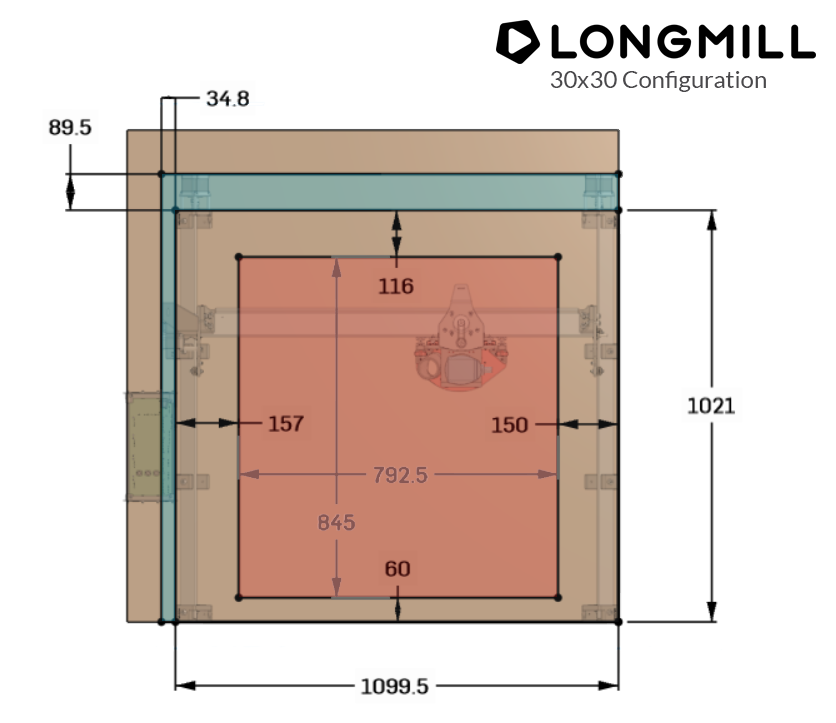
EDIT: Took some time to put together a new graphic which more accurately shows the layout of the machine in the X and Y. Note that:

  • This applies to both LongMill V1 and V2 (pictured is the 30x30 configuration)
  • The red area inside the main box shows the cutting area as an offset from the foot base
  • The blue area outside the main box shows the hanging parts as an offset from the foot base which makes up the total machine outline
  • The area taken up by the control box isnā€™t accounted for in this diagram
  • The foot base of the 12x30 machine is found by shrinking its Y dimension by 500mm
  • The foot base of the 12x12 machine is found by shrinking its Y dimension by 500mm and its X dimension by 500mm
  • If you have our dust shoe attached, your cutting area in the X-dimension will be shrunk by approximately 50mm (about 22.5mm off the left side and 27.5mm off the right side)
  • The width of the foot area is determined by the distance between the middle feet (not the front and back feet) since the middle feet sit slightly wider than the front and back feet do
  • The red cutting area is based about the center-point of the router which is presumed to be mounted inside the 65mm router mount (I have yet to double check that this diagram applies to all router mounts)
  • You can plane an area larger than whatā€™s stated, add your bit diameter to the width and depth of the cutting area to find out what this maximum is
  • Finally, keep in mind that this diagram isnā€™t perfectly exact. I added a bit of a buffer on the cutting area (i.e. shrunk it slightly) since each part has its own manufacturing tolerance and I want to ensure weā€™re providing a reasonable guarantee on what can be expected

@chrismakesstuff the responsiveness and attention to detail you and your team put in to things really sets you apart. Very pleased with my decision and as the machine started coming together in my hands last night I was continually impressed with your engineering and materials choices.

This info is exactly what I was hoping for. Thank you!
-Jeff

@chrismakesstuff As I stood in the long waiting line to get in to the Home Depot today, I found myself pondering the dust shoe. Perhaps the answer will be obvious to me when I am done building it tonight - but is there not an opportunity to have the dust shoe sit out in front of the route rather than along side it? I realize it would be a potential lever that would need to be accounted for, but with a steel arm I would think it shouldnā€™t be a problem? Then you wouldnā€™t lose any of the cutting area? Just a thought.

1 Like

I believe the answer to this is yes, but wanted to double check. This would suggest you can load a 32" wide piece of material and clear the feet on both sides, correct?

The reason I ask is that I had HD cut down my 3/4" sheets of ply today at 32"x48", both for easier transport and handling and because I was hoping to load them to test the vertical cutting layout.

-Jeff

Just in front of my machine now. Tape measure saysā€¦ 920 mm / 36-1/4" space between the insides of the feet.

Perfect, thanks! That means getting a 4x8 cut down in to 3 pieces 32" x 48" will work quite well.

-Jeff

@chrismakesstuff Hi Chris, Iā€™m working on some stuff with the OnShape model and it occurs to me that it may be worth updating that model so the wasteboard shows the new info you added in this thread, then itā€™s right there to help people when designing.

-Jeff

I think itā€™s a bit hidden away right now in a sketch on the waste board model. Iā€™ll look to modify it in a way that visualizes everything better :+1:

I added a cutout to visualize the cutting area of the machine. If you right-click the waste board and select ā€˜Edit in contextā€™ you should see in the feature list on the left side a sketch called ā€œImportant dimensionsā€ and thatā€™s where itā€™s all located

Chris,

I donā€™t seem to have the edit option, but that makes sense since the model is shared in read only mode?

I am loading the model, clicking on the wasteboard and then right clicking to get the menu, correct?

-Jeff

Ahhh, wait I have an idea

EDIT: try checking it out here https://cad.onshape.com/documents/07e5303fe93ccde67c101960/w/c7cd5aa0b4420ce125d689ab/e/e1192a2e2568188e3ef59f17

Yes, that works. No text description visible but fairly obvious what the three areas are. That is very helpful, thanks!

1 Like

Jeff, I just put out a new video which I think youā€™ll find interesting :stuck_out_tongue:

2 Likes

@chrismakesstuff Chris: I have no interest in setting my Mill up to work vertically, but I watched this video in its entirety. I believe that this is your best video yet in terms of explaining the design/cam/cutting process. I donā€™t use CamLabs, but I would recommend that anyone starting out in CamLabs watch this video for a quick tutorial on its setup. The only criticism that I can offer is that it was unclear how you changed the orientation from Z0 being in the centre for design purposes, to using the plate to set it to the lower left corner, then moving it back again before cutting.

ps. Love the carving. :grinning:

1 Like

Yeah, I think it was a bit unclear too. Thanks for the feedback Grant, I actually got to thinking that it might make more sense to try splitting the video up into two separate ones, one on the vertical setup and another on the CAMLab carving, so Iā€™ll be experimenting to see if I can do that tonight with the existing footage :slight_smile:

1 Like